ST7565S
(C) When External Resistors are Used (The V5 Voltage Regulator Internal Resistors Are Not Used) (2)
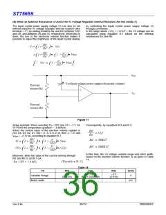
When the external resistor described above are used, adding
a variable resistor as well makes it possible to perform fine
adjustments on Ra’ and Rb’, to set the liquid crystal drive
voltage V5. In this case, the use of the electronic volume
function makes it possible to control the liquid crystal power
supply voltage V5 by commands to adjust the liquid crystal
display brightness.
In the range where | V5 | < | VOUT | the V5 voltage can be
calculated by equation C-1 below based on the R1 and R2
(variable resistor) and R3 settings, where R2 can be
subjected to fine adjustments (ꢃR2).
R3+R2-ΔR2
R1+ΔR2
V
5
= 1 +
(
V
EV
)
R3+R2-ΔR2
R1+ΔR2
α
) ( )
162
= 1 +
(
1 -
V
REG
α
162
∵ VEV
=
1 -
V
( ) ]
REG
[
VDD
V
EV(fixed voltage power supply+electronic volume)
External
resistor R1
Ra'
Rb'
ΔR
2
V
5
External
resistor R2
VR
External
resistor R3
Figure 12
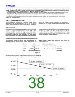
Setup example: When selecting Ta = 25°C and V5 = –5 t o –9
V (using R2) for an ST7565S the temperature gradient
= –0.05%/°C.
When the current flowing VDD and V5 is set to 5 uA,
When the central value for the electronic volume register is
set at (D5, D4, D3, D2, D1, D0) = (1, 0, 0, 0, 0, 0), then α = 31
With this, according to equation C-2, C-3 and C-4,
and VREG = –2.1V. According to equation C-1, when ΔR2 =
0ꢄ, in order to make V5 = –9 V,
R1 = 264kΩ
R2 = 211kΩ
R3 = 925kΩ
R3+R2
R1
31
-9V= 1 +
1 -
(-2.1)
(
) ( )
162
When ΔR2 = R2, in order to make V = –5 V,
R3
31
162
The V5 voltage variable range and notch width based on the
electron volume function is as shown in Table 15.
-5V= 1 +
1 -
(-2.1)
(
R1+R2 ) ( )
Table 15
V5
Variable Range
Notch width
Min
Typ
Max
Units
V
–9
(EV=63)
–7.3
(EV=1,0,0,0,0,0)
–5.5
(EV=0)
56
mV
Ver 0.6c
37/72
2009/09/07

 SITRONIX [ SITRONIX TECHNOLOGY CO., LTD. ]