SiI 1161 PanelLink Receiver
Data Sheet
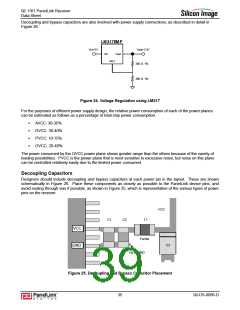
Design Recommendations
The following sections describe recommendations for robust board design with this PanelLink receiver.
Designers should include provision for these circuits in their design, and adjust the specific passive component
values according to the characterization results.
Differences Between SiI 161B and SiI 1161
The RESERVED pin (pin 99) on the SiI 161B is required to be tied HIGH for normal operation. On the SiI 1161
part, pin 99 is defined so that tying it HIGH maintains pin compatibility with the SiI 161B. In this mode, the
SiI 1611 chip meets all operational and timing specifications of the SiI 161B with these exceptions.
ꢁ
Active mode power consumption is higher on the SiI 1161 part due to the new equalizer circuitry. Refer to
Table 1 for actual values.
ꢁ
TFSC is shorter and more predictable due to improved logic implementation.
Selecting SiI 1161 (Programmable) Mode
To use the programmable features of the SiI 1161 part:
ꢁ
Tie pin 99 (the MODE signal) LOW
ꢁ
Tie pin 7 (the I2C_MODE# signal) LOW
The chipset registers are now accessible through standard I2C signaling up to 400kHz through pins 3 (SDA) and
100 (SCL). Note that these pins must be connected through pullups (2kΩ recommended) to 3.3V for correct
operation. In this mode, several pins change their functionality from the SiI 161B standard as shown in Table 17.
Table 17. New Pin Functions for SiI 1161 in Programmable Mode
Pin
99
7
MODE tied HIGH
Chip is in SiI 161B Compatible Mode
STAG_OUT#
MODE tied LOW
Chip is in SiI 1161 I2C Programmable Mode
I2C_MODE#
HIGH: Not Supported
LOW: Chip is in I2C Programmable Mode
3
ST
SDA
SCL
100
OCK_INV
Programmable Mode Reset Recommendations
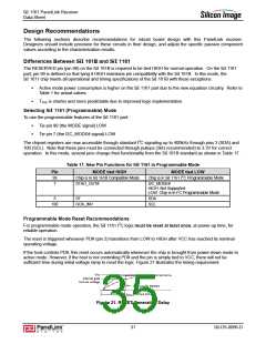
For programmable mode operation, the SiI 1161 I2C logic must be reset at least once, at power-up time, for
reliable operation.
The reset is triggered whenever PD# (pin 2) transitions from LOW to HIGH after VCC has reached its nominal
operating voltage.
If the host controls PD#, this reset occurs automatically whenever the chip is brought from power-down mode to
active mode. However, if the host is not controlling PD# and the pin is simply tied to VCC, there will not be
sufficient time during initial voltage ramp to reset the logic. Figure 21 illustrates the timing requirement.
Vcc
Internal gate
turn-on voltage
Internal I2C RESET
tRESET = 10µs min
Figure 21. RESET Generation Delay
31
SiI-DS-0096-D

 SILICONIMAGE [ Silicon image ]