SiI 1161 PanelLink Receiver
Data Sheet
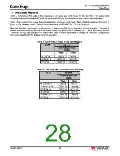
TFT Panel Data Mapping
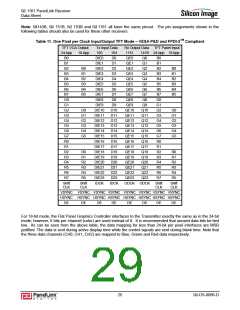
Table 9 summarizes the output data mapping in one pixel per clock mode for the SiI 1161. This output data
mapping is dependent upon the PanelLink transmitters having the exact same type of input data mappings.
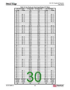
Table 10 summarizes the output data mapping in two pixels per clock mode. More detailed mapping information is
found on the following pages. Refer to application note SiI-AN-0007 for DSTN applications.
Note that the data configuration of the receiver is independent of the configuration of the transmitter. The data is
always transmitted across the link in the same format, regardless of the selection of 12, 24 or 48 bit input format.
Therefore, display-side designers do not need to know how the transmitter is configured. Receiver configuration
is for compatibility with the display, not the transmitter.
Table 9. One Pixel per Clock Mode Data Mapping
DATA
SiI 1161
One Pixel per Clock
Output
18bpp
24bpp
BLUE[7:0]
GREEN[7:0]
RED[7:0]
QE[7:2]
QE[15:10]
QE[23:18]
QE[7:0]
QE[15:8]
QE[23:16]
Table 10. Two Pixel per Clock Mode Data Mapping
DATA
SiI 1161
Two Pixel per Clock
Output
18bpp
QE[7:2]
24bpp
QE[7:0]
BLUE[7:0] – 0
GREEN[7:0] – 0
RED[7:0] – 0
QE[15:10]
QE[23:18]
QO[7:2]
QE[15:8]
QE[23:16]
QO[7:0]
BLUE[7:0] – 1
GREEN[7:0] – 1
RED[7:0] – 1
QO[15:10]
QO[23:18]
QO[15:8]
QO[23:16]
SiI-DS-0096-D
24

 SILICONIMAGE [ Silicon image ]