SiI 1161 PanelLink Receiver
Data Sheet
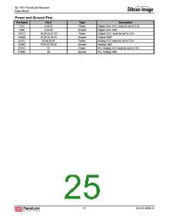
Note: SiI143B, SiI 151B, SiI 153B and SiI 1161 all have the same pinout. The pin assignments shown in the
following tables should also be used for these other receivers.
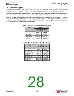
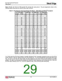
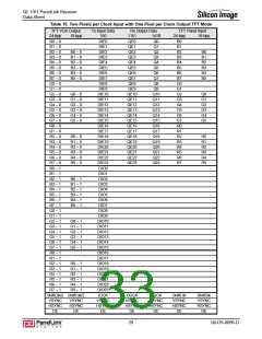
Table 11. One Pixel per Clock Input/Output TFT Mode – VESA P&D and FPDI-2TM Compliant
TFT VGA Output
Tx Input Data
Rx Output Data
TFT Panel Input
24-bpp
B0
18-bpp
160
164
D0
1161
QE0
141B 24-bpp 18-bpp
DIE0
Q0
Q1
B0
B1
B2
B3
B4
B5
B6
B7
G0
G1
G2
G3
G4
G5
G6
G7
R0
R1
R2
R3
R4
R5
R6
R7
B1
DIE1
D1
QE1
B2
B0
B1
B2
B3
B4
B5
DIE2
D2
QE2
Q2
B0
B1
B2
B3
B4
B5
B3
DIE3
D3
QE3
Q3
B4
DIE4
D4
QE4
Q4
B5
DIE5
D5
QE5
Q5
B6
DIE6
D6
QE6
Q6
B7
DIE7
D7
QE7
Q7
G0
G1
G2
G3
G4
G5
G6
G7
R0
R1
R2
R3
R4
R5
R6
R7
DIE8
D8
QE8
Q8
DIE9
D9
QE9
Q9
G0
G1
G2
G3
G4
G5
DIE10
DIE11
DIE12
DIE13
DIE14
DIE15
DIE16
DIE17
DIE18
DIE19
DIE20
DIE21
DIE22
DIE23
IDCK
D10
D11
D12
D13
D14
D15
D16
D17
D18
D19
D20
D21
D22
D23
IDCK
QE10
QE11
QE12
QE13
QE14
QE15
QE16
QE17
QE18
QE19
QE20
QE21
QE22
QE23
Q10
Q11
Q12
Q13
Q14
Q15
Q16
Q17
Q18
Q19
Q20
Q21
Q22
Q23
G0
G1
G2
G3
G4
G5
R0
R1
R2
R3
R4
R5
R0
R1
R2
R3
R4
R5
Shift
CLK
Shift
CLK
ODCK ODCK
Shift
CLK
Shift
CLK
VSYNC VSYNC VSYNC VSYNC VSYNC VSYNC VSYNC VSYNC
HSYNC HSYNC HSYNC HSYNC HSYNC HSYNC HSYNC HSYNC
DE
DE
DE
DE
DE
DE
DE
DE
For 18-bit mode, the Flat Panel Graphics Controller interfaces to the Transmitter exactly the same as in the 24-bit
mode; however, 6 bits per channel (color) are used instead of 8. It is recommended that unused data bits be tied
low. As can be seen from the above table, the data mapping for less than 24-bit per pixel interfaces are MSB
justified. The data is sent during active display time while the control signals are sent during blank time. Note that
the three data channels (CH0, CH1, CH2) are mapped to Blue, Green and Red data respectively.
25
SiI-DS-0096-D

 SILICONIMAGE [ Silicon image ]