EFM32G Data Sheet
Pin Definitions
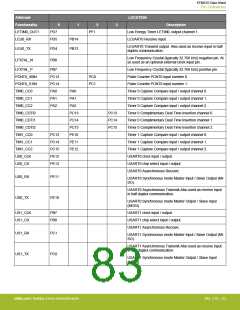
Alternate
LOCATION
Functionality
LETIM0_OUT1
LEU0_RX
0
1
2
3
Description
PD7
PD5
PF1
Low Energy Timer LETIM0, output channel 1.
LEUART0 Receive input.
PB14
LEUART0 Transmit output. Also used as receive input in half
duplex communication.
LEU0_TX
PD4
PB13
Low Frequency Crystal (typically 32.768 kHz) negative pin. Al-
so used as an optional external clock input pin.
LFXTAL_N
PB8
PB7
LFXTAL_P
PCNT0_S0IN
PCNT0_S1IN
TIM0_CC0
TIM0_CC1
TIM0_CC2
TIM0_CDTI0
TIM0_CDTI1
TIM0_CDTI2
TIM1_CC0
TIM1_CC1
TIM1_CC2
US0_CLK
Low Frequency Crystal (typically 32.768 kHz) positive pin.
Pulse Counter PCNT0 input number 0.
PC13
PC14
PA0
PC0
PC1
Pulse Counter PCNT0 input number 1.
PA0
Timer 0 Capture Compare input / output channel 0.
Timer 0 Capture Compare input / output channel 1.
Timer 0 Capture Compare input / output channel 2.
Timer 0 Complimentary Deat Time Insertion channel 0.
Timer 0 Complimentary Deat Time Insertion channel 1.
Timer 0 Complimentary Deat Time Insertion channel 2.
Timer 1 Capture Compare input / output channel 0.
Timer 1 Capture Compare input / output channel 1.
Timer 1 Capture Compare input / output channel 2.
USART0 clock input / output.
PA1
PA1
PA2
PA2
PC13
PC14
PC15
PE10
PE11
PE12
PC13
PC14
PC15
PC13
PC14
PC15
PE12
PE13
US0_CS
USART0 chip select input / output.
USART0 Asynchronous Receive.
US0_RX
US0_TX
PE11
PE10
USART0 Synchronous mode Master Input / Slave Output (MI-
SO).
USART0 Asynchronous Transmit.Also used as receive input
in half duplex communication.
USART0 Synchronous mode Master Output / Slave Input
(MOSI).
US1_CLK
US1_CS
PB7
PB8
USART1 clock input / output.
USART1 chip select input / output.
USART1 Asynchronous Receive.
US1_RX
US1_TX
PC1
PC0
USART1 Synchronous mode Master Input / Slave Output (MI-
SO).
USART1 Asynchronous Transmit.Also used as receive input
in half duplex communication.
USART1 Synchronous mode Master Output / Slave Input
(MOSI).
silabs.com | Building a more connected world.
Rev. 2.10 | 83

 SILICON [ SILICON ]