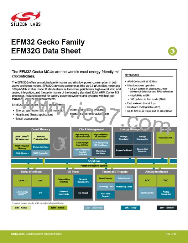
EFM32G Data Sheet
Electrical Characteristics
Table 4.21. I2C Fast-mode Plus (Fm+)
Parameter
Symbol
Min
Typ
Max
Unit
10001
—
SCL clock frequency
fSCL
0
—
kHz
SCL clock low time
tLOW
0.5
0.26
50
—
—
—
—
—
—
—
—
µs
µs
ns
ns
µs
µs
µs
µs
SCL clock high time
tHIGH
—
SDA set-up time
tSU,DAT
tHD,DAT
tSU,STA
tHD,STA
tSU,STO
tBUF
—
SDA hold time
8
—
Repeated START condition set-up time
(Repeated) START condition hold time
STOP condition set-up time
0.26
0.26
0.26
0.5
—
—
—
Bus free time between a STOP and a START
condition
—
Note:
1. For the minimum HFPERCLK frequency required in Fast-mode Plus, see the I2C chapter in the EFM32G Reference Manual.
4.16 Digital Peripherals
Table 4.22. Digital Peripherals
Parameter
Symbol
IUSART
IUART
ILEUART
II2C
Test Condition
Min
—
—
—
—
—
—
—
—
—
—
—
—
—
—
Typ
7.5
Max
—
—
—
—
—
—
—
—
—
—
—
—
—
—
Unit
µA/MHz
µA/MHz
nA
USART current
UART current
LEUART current
I2C current
USART idle current, clock enabled
UART idle current, clock enabled
LEUART idle current, clock enabled
I2C idle current, clock enabled
TIMER_0 idle current, clock enabled
LETIMER idle current, clock enabled
PCNT idle current, clock enabled
RTC idle current, clock enabled
LCD idle current, clock enabled
AES idle current, clock enabled
GPIO idle current, clock enabled
EBI idle current, clock enabled
PRS idle current
5.63
150
6.25
8.75
150
100
100
100
2.5
µA/MHz
µA/MHz
nA
TIMER current
LETIMER current
PCNT current
RTC current
LCD current
AES current
GPIO current
EBI current
ITIMER
ILETIMER
IPCNT
IRTC
nA
nA
ILCD
nA
IAES
µA/MHz
µA/MHz
µA/MHz
µA/MHz
µA/MHz
IGPIO
IEBI
5.31
1.56
2.81
8.12
PRS current
DMA current
IPRS
IDMA
Clock enable
Note: Please refer to the application note "AN0002 EFM32 Hardware Design Considerations" forguidelines on designing Printed Circuit
Boards (PCB's) for the EFM32G.
silabs.com | Building a more connected world.
Rev. 2.10 | 78
