EFM32G Data Sheet
TQFP64 Package Specifications
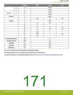
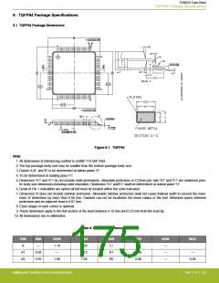
8. TQFP64 Package Specifications
8.1 TQFP64 Package Dimensions
F
C
L
Figure 8.1. TQFP64
Note:
1. All dimensions & tolerancing confirm to ASME Y14.5M-1994.
2. The top package body size may be smaller than the bottom package body size.
3. Datum 'A,B', and 'B' to be determined at datum plane 'H'.
4. To be determined at seating place 'C'.
5. Dimension 'D1' and 'E1' do not include mold protrusions. Allowable protrusion is 0.25mm per side.'D1' and 'E1' are maximum plas-
tic body size dimension including mold mismatch. Dimension 'D1' and'E1' shall be determined at datum plane 'H'.
6. Detail of Pin 1 indicatifier are option all but must be located within the zone indicated.
7. Dimension 'b' does not include dambar protrusion. Allowable dambar protrusion shall not cause thelead width to exceed the maxi-
mum 'b' dimension by more than 0.08 mm. Dambar can not be locatedon the lower radius or the foot. Minimum space between
protrusion and an adjacent lead is 0.07 mm.
8. Exact shape of each corner is optional.
9. These dimension apply to the flat section of the lead between 0.10 mm and 0.25 mm from the lead tip.
10. All dimensions are in millimeters.
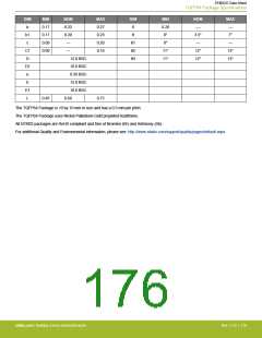
Table 8.1. QFP64 (Dimensions in mm)
DIM
A
MIN
—
NOM
1.10
—
MAX
1.20
0.15
1.05
DIM
L1
MIN
NOM
—
MAX
A1
A2
0.05
0.95
R1
R2
0.08
0.08
—
—
1.00
—
0.20
silabs.com | Building a more connected world.
Rev. 2.10 | 175

 SILICON [ SILICON ]