C8051F52x-53x
Mode, but power consumption is slightly increased. High-Speed Analog Mode is enabled by setting the
CPnHIQE bit in CPTnMD.
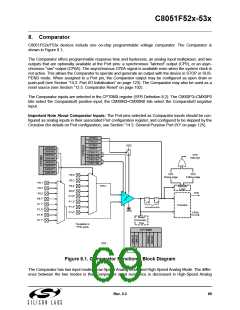
The Comparator output can be polled in software, used as an interrupt source, internal oscillator suspend
awakening source and/or routed to a Port pin. When routed to a Port pin, the Comparator output is avail-
able asynchronous or synchronous to the system clock; the asynchronous output is available even in
STOP or SUSPEND mode (with no system clock active). When disabled, the Comparator output (if
assigned to a Port I/O pin via the Crossbar) defaults to the logic low state, and its supply current falls to
less than 100 nA. See Section “14.1. Priority Crossbar Decoder” on page 119 for details on configuring
Comparator outputs via the digital Crossbar. Comparator inputs can be externally driven from –0.25 V to
(V ) + 0.25 V without damage or upset. The complete Comparator electrical specifications are given in
DD
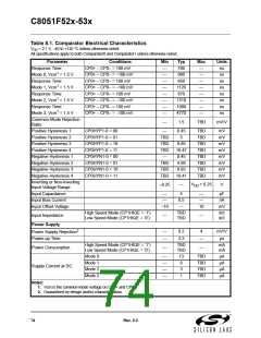
Table 8.1.
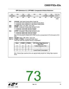
The Comparator response time may be configured in software via the CPTnMD register (see SFR Defini-
tion 8.3). Selecting a longer response time reduces the Comparator supply current. See Table 8.1 for com-
plete timing and current consumption specifications.
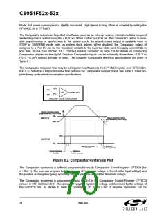
CP0+
VIN+
VIN-
+
CP0
_
OUT
CP0-
CIRCUIT CONFIGURATION
Positive Hysteresis Voltage
(Programmed with CP0HYP Bits)
VIN-
Negative Hysteresis Voltage
(Programmed by CP0HYN Bits)
INPUTS
VIN+
VOH
OUTPUT
VOL
Negative Hysteresis
Disabled
Maximum
Negative Hysteresis
Positive Hysteresis
Disabled
Maximum
Positive Hysteresis
Figure 8.2. Comparator Hysteresis Plot
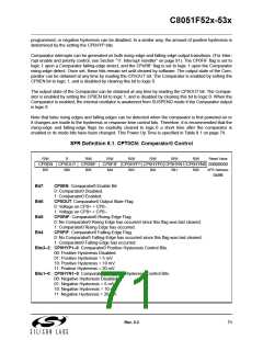
The Comparator hysteresis is software-programmable via its Comparator Control register CPT0CN (for
n = 0 or 1). The user can program both the amount of hysteresis voltage (referred to the input voltage) and
the positive and negative-going symmetry of this hysteresis around the threshold voltage.
The Comparator hysteresis is programmed using Bits3–0 in the Comparator Control Register CPT0CN
(shown in SFR Definition 8.1). The amount of negative hysteresis voltage is determined by the settings of
the CP0HYN bits. As shown in Table 8.1, settings of 20, 10 or 5 mV of negative hysteresis can be
70
Rev. 0.3

 SILICON [ SILICON ]