C8051F52x-53x
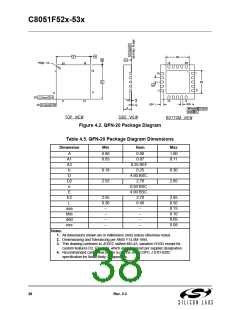
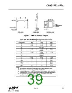
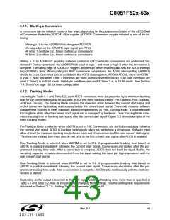
Figure 4.3. QFN-10 Package Diagram
Table 4.6. QFN-10 Package Diagram Dimensions
Dimension
Min
Nom
Max
A
A1
A3
b
0.80
0.03
0.90
0.07
1.00
0.11
0.25 REF
0.25
0.18
0.30
D
3.00 BSC.
1.646
0.50 BSC.
3.00 BSC.
2.384
0.40
D2
e
1.496
1.796
E
E2
L
2.234
0.30
—
2.534
0.50
0.15
0.15
0.05
0.08
aaa
bbb
ddd
eee
—
—
—
—
—
—
—
Notes:
1. All dimensions shown are in millimeters (mm) unless otherwise noted.
2. Dimensioning and Tolerancing per ANSI Y14.5M-1994.
3. This drawing conforms to JEDEC outline MO-243, variation VEED except for
custom features D2, E2, and L which are toleranced per supplier designation.
4. Recommended card reflow profile is per the JEDEC/IPC J-STD-020C
specification for Small Body Components.
Rev. 0.3
39

 SILICON [ SILICON ]