C8051F52x-53x
17.4.8. Error Detection and Handling
The LIN peripheral generates an interrupt request and stops the processing of the current frame if it
detects an error. The application has to check the type of error by processing the error register (LINERR).
After that, it has to reset the error register (LINERR) and the ERROR bit in status register (LINST) by writ-
ing a '1' to the RSTERR bit in the control register (LINCTRL). Starting a new message with the LIN periph-
eral selected as master or sending a Wakeup signal with the LIN peripheral selected as a master or slave
is possible only if ERROR bit in status register is set to '0'.
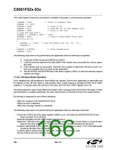
17.4.9. LIN Master Mode Operation
The operation setup of the LIN peripheral in Master mode requires that the LIN bus is not active (ACTIVE
bit in LINST register set to ‘0’).
The master is responsible for the schedule of the messages. It sends the header of each frame that con-
tains SYNC BREAK FIELD, SYNC FIELD and IDENTIFIER FIELD. The steps for scheduling a message
frame are explained in the following paragraphs.
1. Load the 6-bit Identifier into the ID register (LINID).
2. Load the “data length” in the LINSIZE register (number of data bytes or value “1111b” if the data length
should be decoded from the identifier) and set the checksum type (classic or enhanced, defined by the
ENHCHK bit also in the LINSIZE register).
3. Adjust the TXRX bit (LINCTRL.5):
“1” - If the current frame is a transmit operation for the master.
“0” – If the current frame is a receive operation for the master.
4. Load the data bytes to transmit into the data buffer (LINDT1 to LINDT8 and transmit operation only).
5. The STREQ bit (LINCTRL) is set to start the message transfer. After that the LIN peripheral schedules
the message frame and request an interrupt if the message transfer is successfully completed or if an error
is occurred.
6. The following steps have to be performed by the application when an interrupt is requested.
6a. Check the DONE bit and the ERROR bit (LINST)
6b. Load the received data from the data buffer if the transfer was successful (for receive operation only).
6c. If the transfer was not successful, check the error register to determine the kind of error. Further error
handling has to be done by the application.
6d. Set the RSTINT and RSTERR bits in the status register (LINST) to reset the interrupt request and the
error flags.
17.4.10.LIN Slave Mode Operation
Once the Baud rate has been selected and the checksum type selected (classic or enhanced) the LIN
peripheral can start receiving messages.
168
Rev. 0.3

 SILICON [ SILICON ]