C8051F52x-53x
When the crystal oscillator is first enabled, the oscillator amplitude detection circuit requires a settling time
to achieve proper bias. Introducing a delay of 1 ms between enabling the oscillator and checking the
XTLVLD bit will prevent a premature switch to the external oscillator as the system clock. Switching to the
external oscillator before the crystal oscillator has stabilized can result in unpredictable behavior. The rec-
ommended procedure is:
Step 1. Configure XTAL1 and XTAL2 pins by writing ‘1' to the port latch.
Step 2. Configure XTAL1 and XTAL2 as analog inputs.
Step 3. Enable the external oscillator.
Step 4. Wait at least 1 ms.
Step 5. Poll for XTLVLD => '1'.
Step 6. Switch the system clock to the external oscillator.
Note: Tuning-fork crystals may require additional settling time before XTLVLD returns a valid result.
The capacitors shown in the external crystal configuration provide the load capacitance required by the
crystal for correct oscillation. These capacitors are "in series" as seen by the crystal and "in parallel" with
the stray capacitance of the XTAL1 and XTAL2 pins.
Note: The load capacitance depends upon the crystal and the manufacturer. Please refer to the crystal
data sheet when completing these calculations.
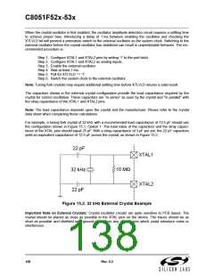
For example, a tuning-fork crystal of 32 kHz with a recommended load capacitance of 12.5 pF should use
the configuration shown in Figure 15.1, Option 1. The total value of the capacitors and the stray capaci-
tance of the XTAL pins should equal 25 pF. With a stray capacitance of 3 pF per pin, the 22 pF capacitors
yield an equivalent capacitance of 12.5 pF across the crystal, as shown in Figure 15.2.
22 pF
XTAL1
Ω
10 MΩ
32 kHz
22 pF
XTAL2
Figure 15.2. 32 kHz External Crystal Example
Important Note on External Crystals: Crystal oscillator circuits are quite sensitive to PCB layout. The
crystal should be placed as close as possible to the XTAL pins on the device. The traces should be as
short as possible and shielded with ground plane from any other traces which could introduce noise or
interference.
138
Rev. 0.3

 SILICON [ SILICON ]