C8051F52x-53x
15.2. External Oscillator Drive Circuit
The external oscillator circuit may drive an external crystal, ceramic resonator, capacitor, or RC network. A
CMOS clock may also provide a clock input. For a crystal or ceramic resonator configuration, the crys-
tal/resonator must be wired across the XTAL1 and XTAL2 pins as shown in Option 1 of Figure 15.1. A
10 MΩ resistor also must be wired across the XTAL1 and XTAL2 pins for the crystal/resonator configura-
tion. In RC, capacitor, or CMOS clock configuration, the clock source should be wired to the XTAL2 pin as
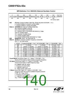
shown in Option 2, 3, or 4 of Figure 15.1. The type of external oscillator must be selected in the OSCXCN
register, and the frequency control bits (XFCN) must be selected appropriately (see SFR
Definition 15.4. OSCXCN: External Oscillator Control).
Important Note on External Oscillator Usage: Port pins must be configured when using the external
oscillator circuit. When the external oscillator drive circuit is enabled in crystal/resonator mode, Port pins
P0.7 and P1.0 (‘F53x) or P0.2 and P0.3 (‘F52x) are used as XTAL1 and XTAL2 respectively. When the
external oscillator drive circuit is enabled in capacitor, RC, or CMOS clock mode, Port pin P1.0 (‘F530) or
P0.3 (‘F52x) is used as XTAL2. The Port I/O Crossbar should be configured to skip the Port pins used by
the oscillator circuit; see Section “14.1. Priority Crossbar Decoder” on page 119 for Crossbar configuration.
Additionally, when using the external oscillator circuit in crystal/resonator, capacitor, or RC mode, the asso-
ciated Port pins should be configured as analog inputs. In CMOS clock mode, the associated pin should
be configured as a digital input. See Section “14.2. Port I/O Initialization” on page 123 for details on Port
input mode selection.
15.2.1. Clocking Timers Directly Through the External Oscillator
The external oscillator source divided by eight is a clock option for the timers (Section “19. Timers” on
page 185) and the Programmable Counter Array (PCA) (Section “20. Programmable Counter Array
(PCA0)” on page 199). When the external oscillator is used to clock these peripherals, but is not used as
the system clock, the external oscillator frequency must be less than or equal to the system clock fre-
quency. In this configuration, the clock supplied to the peripheral (external oscillator / 8) is synchronized
with the system clock; the jitter associated with this synchronization is limited to ±0.5 system clock cycles.
15.2.2. External Crystal Example
If a crystal or ceramic resonator is used as an external oscillator source for the MCU, the circuit should be
configured as shown in Figure 15.1, Option 1. The External Oscillator Frequency Control value (XFCN)
should be chosen from the Crystal column of the table in SFR Definition 15.4. For example, a 12 MHz crys-
tal requires an XFCN setting of 111b.
Rev. 0.3
137

 SILICON [ SILICON ]