C8051F39x/37x
20.1. MCU Interrupt Sources and Vectors
The C8051F39x/37x MCUs support 18 interrupt sources. Software can simulate an interrupt by setting any
interrupt-pending flag to logic 1. If interrupts are enabled for the flag, an interrupt request will be generated
and the CPU will vector to the ISR address associated with the interrupt-pending flag. MCU interrupt
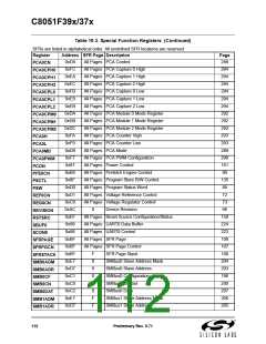
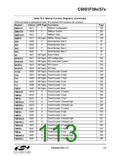
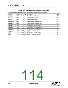
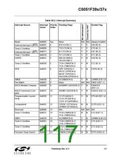
sources, associated vector addresses, priority order and control bits are summarized in Table 20.2. Refer
to the datasheet section associated with a particular on-chip peripheral for information regarding valid
interrupt conditions for the peripheral and the behavior of its interrupt-pending flag(s).
20.1.1. Interrupt Priorities
Each interrupt source can be individually programmed to one of four priority levels. This differs from the
traditional two priority levels on the 8051 core. However, the implementation of the extra levels is back-
wards-compatible with legacy 8051 code.
An interrupt service routine can be preempted by any interrupt of higher priority. Interrupts at the highest
priority level cannot be preempted. Each interrupt has two associated priority bits which are used to config-
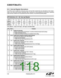
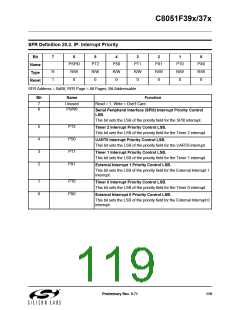
ure the priority level. For backwards compatibility, the bits are spread across two different registers. The
LSBs of the priority setting are stored in the IP, EIP1 and EIP2 registers, while the MSBs are store in the
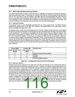
IPH, EIP1H and EIP2H registers. Priority levels according to the MSB and LSB are decoded in Table 20.1.
The lowest priority setting is the default for all interrupts. If two or more interrupts are recognized simulta-
neously, the interrupt with the highest priority is serviced first. If both interrupts have the same priority level,
a fixed priority order is used to arbitrate, given in Table 20.2. If legacy 8051 operation is desired, the bits of
the “High” priority registers (IPH, EIP1H and EIP2H) should all be configured to 0 (this is the reset value of
these registers).
Priority MSB
Priority LSB
Priority Level
(from IPH, EIP1H or
EIP2H)
(from IP, EIP1 or
EIP2)
0
0
1
1
0
1
0
1
Priority 0 (lowest priority, default)
Priority 1
Priority 2
Priority 3 (highest priority)
Table 20.1. Configurable Interrupt Priority Decoding
20.1.2. Interrupt Latency
Interrupt response time depends on the state of the CPU when the interrupt occurs. Pending interrupts are
sampled and priority decoded each system clock cycle. Therefore, the fastest possible response time is 5
system clock cycles: 1 clock cycle to detect the interrupt and 4 clock cycles to complete the LCALL to the
ISR. If an interrupt is pending when a RETI is executed, a single instruction is executed before an LCALL
is made to service the pending interrupt. Therefore, the maximum response time for an interrupt (when no
other interrupt is currently being serviced or the new interrupt is of greater priority) occurs when the CPU is
performing an RETI instruction followed by a DIV as the next instruction. In this case, the response time is
18 system clock cycles: 1 clock cycle to detect the interrupt, 5 clock cycles to execute the RETI, 8 clock
cycles to complete the DIV instruction and 4 clock cycles to execute the LCALL to the ISR. If the CPU is
executing an ISR for an interrupt with equal or higher priority, the new interrupt will not be serviced until the
current ISR completes, including the RETI and following instruction. If more than one interrupt is pending
when the CPU exits an ISR, the CPU will service the next highest priority interrupt that is pending.
116
Preliminary Rev. 0.71

 SILICON [ SILICON ]