C8051F39x/37x
20. Interrupts
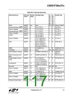
The C8051F39x/37x includes an extended interrupt system supporting multiple interrupt sources with four
priority levels. The allocation of interrupt sources between on-chip peripherals and external input pins var-
ies according to the specific version of the device. Each interrupt source has one or more associated inter-
rupt-pending flag(s) located in an SFR. When a peripheral or external source meets a valid interrupt
condition, the associated interrupt-pending flag is set to logic 1.
If interrupts are enabled for the source, an interrupt request is generated when the interrupt-pending flag is
set. As soon as execution of the current instruction is complete, the CPU generates an LCALL to a prede-
termined address to begin execution of an interrupt service routine (ISR). Each ISR must end with an RETI
instruction, which returns program execution to the next instruction that would have been executed if the
interrupt request had not occurred. If interrupts are not enabled, the interrupt-pending flag is ignored by the
hardware and program execution continues as normal. (The interrupt-pending flag is set to logic 1 regard-
less of the interrupt's enable/disable state.)
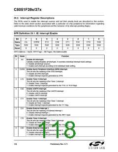
Each interrupt source can be individually enabled or disabled through the use of an associated interrupt
enable bit in an SFR (IE, EIE1, and EIE2). However, interrupts must first be globally enabled by setting the
EA bit (IE.7) to logic 1 before the individual interrupt enables are recognized. Setting the EA bit to logic 0
disables all interrupt sources regardless of the individual interrupt-enable settings.
Note: Any instruction that clears a bit to disable an interrupt should be immediately followed by an instruc-
tion that has two or more opcode bytes. Using EA (global interrupt enable) as an example:
// in 'C':
EA = 0; // clear EA bit.
EA = 0; // this is a dummy instruction with two-byte opcode.
; in assembly:
CLR EA ; clear EA bit.
CLR EA ; this is a dummy instruction with two-byte opcode.
For example, if an interrupt is posted during the execution phase of a "CLR EA" opcode (or any instruction
which clears a bit to disable an interrupt source), and the instruction is followed by a single-cycle instruc-
tion, the interrupt may be taken. However, a read of the enable bit will return a '0' inside the interrupt ser-
vice routine. When the bit-clearing opcode is followed by a multi-cycle instruction, the interrupt will not be
taken.
Some interrupt-pending flags are automatically cleared by the hardware when the CPU vectors to the ISR.
However, most are not cleared by the hardware and must be cleared by software before returning from the
ISR. If an interrupt-pending flag remains set after the CPU completes the return-from-interrupt (RETI)
instruction, a new interrupt request will be generated immediately and the CPU will re-enter the ISR after
the completion of the next instruction.
Preliminary Rev. 0.71
115

 SILICON [ SILICON ]