GP1A52HRJ00F
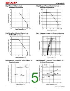
Fig.1 Forward Current vs.
Fig.2 Output Power Dissipation vs.
Ambient Temperature
Ambient Temperature
60
300
50
40
30
250
200
150
100
20
10
50
0
0
−25
0
25
50
75 85 100
−25
0
25
50
75 85 100
Ambient temperature Ta (˚C)
Ambient temperature Ta (C)
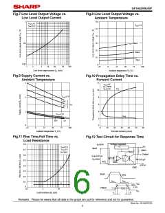
Fig.3 Low Level Output Current vs.
Fig.4 Forward Current vs. Forward Voltage
Ambient Temperature
60
Ta=75˚C
50˚C
25˚C
50
40
30
20
0˚C
−25˚C
100
10
10
0
1
0
0.5
1
1.5
2
2.5
3
3.5
−20
0
25
50
75 85 100
Foward voltage VF (V)
Ambient temperature Ta (˚C)
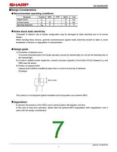
Fig.5 Relative Threshold Input Current vs.
Supply Voltage
Fig.6 Relative Threshold Input Current vs.
Ambient Temperature
1.1
1.8
VCC=5V
IFLH=1
at Ta=25˚C
Ta=25˚C
IFLH=1
at VCC=5V
1.6
IFLH
1
1.4
0.9
IFLH
1.2
0.8
IFHL
1
IFHL
0.7
0.8
0.6
0.5
0.6
0.4
0
5
10
15
20
25
−25
0
25
50
75
100
Supply voltage VCC (V)
Ambient temperature Ta (˚C)
Sheet No.: D3-A03701EN
5

 SHARP [ SHARP ELECTRIONIC COMPONENTS ]