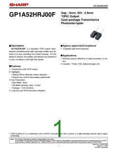
GP1A52HRJ00F
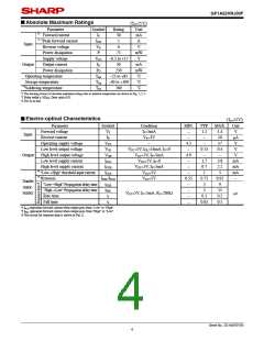
Absolute Maximum Ratings
■
(T 25˚C)
=
a
Parameter
Symbol
Rating
Unit
mA
A
∗
∗
1
Forward current
IF
IFM
VR
P
50
1
1, 2Peak forward current
Reverse voltage
Power dissipation
Supply voltage
Input
6
V
75
mW
V
VCC
IO
0.5 to 17
−
+
Output
Output current
50
mA
mW
˚C
Power dissipation
PO
250
Operating temperature
Storage temperature
3Soldering temperature
Topr
Tstg
Tsol
25 to 85
+
−
40 to 100
˚C
−
+
∗
260
˚C
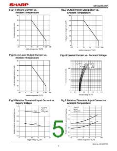
∗1 The derating factors of absolute maximum ratings due to ambient temperature are shown in Fig. 1, 2, 3
∗2 Pulse width ≤ 100 s, Duty ratio 0.01
μ
=
∗3 For 5s or less
Electro-optical Characteristics
■
(T 25˚C)
=
a
Parameter
Symbol
VF
Condition
5mA
MIN.
−
TYP. MAX.
Unit
V
Forward voltage
I
1.1
−
1.4
10
17
0.4
−
=
F
Input
Reverse current
IR
VR 3V
A
μ
=
−
Operating supply voltage
Low level output voltage
High level output voltage
Low level supply current
High level supply current
VCC
VOL
VOH
ICCL
ICCH
IFLH
IFHL/IFLH
tPLH
tPHL
tr
4.5
−
V
−
−
VCC 5V, I 16mA, I 0
=
F
0.15
−
V
V
=
=
OL
Output
VCC 5V, I 5mA
4.9
−
=
=
F
VCC 5V, I
0
=
F
1.7
0.7
1
3.8
2.2
5
mA
mA
mA
−
=
VCC 5V, I 5mA
=
=
−
F
∗
∗
4 "Low High" threshold input current
VCC 5V
→
=
−
5 Hysteresis
VCC 5V
0.55
−
0.75
3
0.95
9
=
Transfer
charac-
teristics
6
∗
"Low High" Propagation delay time
→
"High Low" Propagation delay time
5
15
0.5
0.5
→
−
VCC 5V, I 5mA, R 280
s
μ
=
=
=
L
Ω
F
Rise time
0.1
0.05
−
Fall time
tf
−
∗4 IFLH represents forward current when output goes from "Low" to "High".
∗5 IFHL represents forward current when output goes from "High" to "Low".
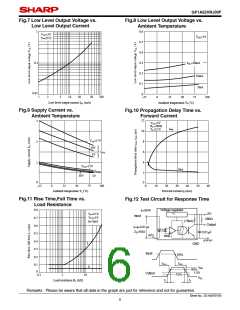
∗6 Test circuit for response time is shown in Fig.12.
Sheet No.: D3-A03701EN
4

 SHARP [ SHARP ELECTRIONIC COMPONENTS ]