SX1231
ADVANCED COMMUNICATIONS & SENSING
DATASHEET
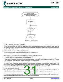
SX1231 in Rx mode
Preamble-modulated input signal
Signal level > Sensitivity
Set FeiStart
= 1
No
FeiDone
= 1
Yes
Read
FeiValue
Figure 12. FEI Process
3.5.14. Automatic Frequency Correction
The AFC is based on the FEI block, and therefore the same input signal and receiver setting conditions apply. When the
AFC procedure is done, AfcValue is directly subtracted to the register that defines the frequency of operation of the chip,
F
. The AFC can be launched:
RF
Each time the receiver is enabled, if AfcAutoOn = 1
Upon user request, by setting bit AfcStart in RegAfcFei, if AfcAutoOn = 0
When the AFC is automatically triggered (AfcAutoOn = 1), the user has the option to:
Clear the former AFC correction value, if AfcAutoClearOn = 1
Start the AFC evaluation from the previously corrected frequency. This may be useful in systems in which the LO keeps
on drifting in the “same direction”. Ageing compensation is a good example.
The SX1231 offers an alternate receiver bandwidth setting during the AFC phase, to accommodate large LO drifts. If the
user considers that the received signal may be out of the receiver bandwidth, a higher channel filter bandwidth can be
programmed in RegAfcBw, at the expense of the receiver noise floor, which will impact upon sensitivity.
3.5.15. Temperature Sensor
When temperature is measured, the receiver ADC is used to digitize the sensor response. Most receiver blocks are
disabled, and temperature measurement can only be triggered in Standby or Frequency Synthesizer modes.
The response of the temperature sensor is -1°C / Lsb. A CMOS temperature sensor is not accurate by nature, therefore it
should be calibrated at ambient temperature for precise temperature readings.
Rev 2 - Nov 2009
Page 31
www.semtech.com

 SEMTECH [ SEMTECH CORPORATION ]