SX1231
ADVANCED COMMUNICATIONS & SENSING
4. Operating Modes
DATASHEET
4.1. Basic Modes
The circuit can be set in 5 different basic modes which are described in Table 14.
By default, when switching from a mode to another one, the sub-blocks are woken up according to a pre-defined and
optimized sequence. Alternatively, these operating modes can be selected directly by disabling the automatic sequencer
(SequencerOff in RegOpMode = 1).
Table 14 Basic Transceiver Modes
ListenOn
Mode
Selected mode
Enabled blocks
in RegOpMode
in RegOpMode
0
0
0
0
0
1
0 0 0
0 0 1
0 1 0
0 1 1
1 0 0
x
Sleep Mode
Stand-by Mode
FS Mode
None
Top regulator and crystal oscillator
Frequency synthesizer
Transmit Mode
Receive Mode
Listen Mode
Frequency synthesizer and transmitter
Frequency synthesizer and receiver
See Listen Mode, section 4.3
4.2. Automatic Sequencer and Wake-Up Times
By default, when switching from one operating mode to another, the circuit takes care of the sequence of events in such a
way that the transition timing is optimized. For example, when switching from Sleep mode to Transmit mode, the SX1231
goes first to Standby mode (XO started), then to frequency synthesizer mode, and finally, when the PLL has locked, to
transmit mode. Entering transmit mode is also made according to a predefined sequence starting with the wake-up of the
PA regulator before applying a ramp-up on the PA and generating the DCLK clock.
The crystal oscillator wake-up time, TS_OSC, is directly related to the time for the crystal oscillator to reach its steady
state. It depends notably on the crystal characteristics.
The frequency synthesizer wake-up time, TS_FS, is directly related to the time needed by the PLL to reach its steady
state. The signal PLL_LOCK, provided on an external pin, gives an indication of the lock status. It goes high when the
PLL reaches its locking range.
Four specific cases can be highlighted:
Transmitter Wake Up time from Sleep mode
= TS_OSC + TS_FS + TS_TR
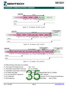
Receiver Wake Up time from Sleep mode
= TS_OSC + TS_FS + TS_RE
Receiver Wake Up time from Sleep mode, AGC enabled
Receiver Wake Up time from Sleep mode, AGC and AFC enabled
= TS_OSC + TS_FS + TS_RE_AGC
= TS_OSC + TS_FS + TS_RE_AGC&AFC
These timings are details in sections 4.2.1 and 4.2.3.
In applications where the target average power consumption, or the target startup time, do not require setting the SX1231
in the lowest power modes (Sleep or Standby), the respective timings TS_OSC and TS_FS in the former equations can be
omited.
Rev 2 - Nov 2009
Page 33
www.semtech.com

 SEMTECH [ SEMTECH CORPORATION ]