SX1231
ADVANCED COMMUNICATIONS & SENSING
DATASHEET
The new floor threshold value found during this test should be the value used for OOK reception with those receiver
settings.
3.5.11.2. Optimizing OOK Demodulator for Fast Fading Signals
A sudden drop in signal strength can cause the bit error rate to increase. For applications where the expected signal drop
can be estimated, the following OOK demodulator parameters OokPeakThreshStep and OokPeakThreshDec can be
optimized as described below for a given number of threshold decrements per bit. Refer to RegOokPeak to access those
settings.
3.5.11.3. Alternative OOK Demodulator Threshold Modes
In addition to the Peak OOK threshold mode, the user can alternatively select two other types of threshold detectors:
Fixed Threshold: The value is selected through OokFixedThresh
Average Threshold: Data supplied by the RSSI block is averaged, and this operation mode should only be used with
DC-free encoded data.
3.5.12. Bit Synchronizer
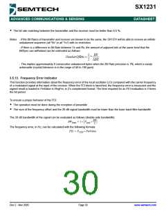
The Bit Synchronizer is a block that provides a clean and synchronized digital output, free of glitches. Its output is made
available on pin DIO1/DCLK in Continuous mode and can be disabled through register settings. However, for optimum
receiver performance its use when running Continuous mode is strongly advised.
The Bit Synchronizer is automatically activated in Packet mode. Its bit rate is controlled by BitRateMsb and BitRateLsb in
RegBitrate.
Raw demodulator
output
(FSK or OOK)
DATA
BitSync Output
To pin DATA and
DCLK in continuous
mode
DCLK
Figure 11. Bit Synchronizer Description
To ensure correct operation of the Bit Synchronizer, the following conditions have to be satisfied:
A preamble (0x55 or 0xAA) of 12 bits is required for synchronization (from the RxReady interrupt)
The subsequent payload bit stream must have at least one transition form '0' to '1' or '1' to '0 every 16 bits during data
transmission
Rev 2 - Nov 2009
Page 29
www.semtech.com

 SEMTECH [ SEMTECH CORPORATION ]