SX1231
ADVANCED COMMUNICATIONS & SENSING
DATASHEET
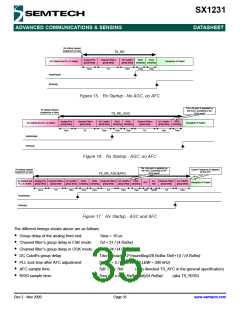
Rx startup request
(sequencer or user)
TS_RE
Analog FE’s
group delay
Channel Filter’s
group delay
DC Cutoff’s
group delay sampling sampling
RSSI
RSSI
XO Started and PLL is locked
Reception of Packet
Tana
Tcf
Tdcc
Trssi
Trssi
ModeReady
RxReady
Figure 15. Rx Startup - No AGC, no AFC
The LNA gain is adjusted by
the AGC, according to the
RSSI result
Rx startup request
(sequencer or user)
TS_RE_AGC
Analog FE’s
group delay
Channel Filter’s
group delay
DC Cutoff’s
group delay sampling sampling
RSSI
RSSI
Channel Filter’s
group delay
DC Cutoff’s
group delay sampling
RSSI
XO Started and PLL is locked
Reception of Packet
Tana
Tcf
Tdcc
Trssi
Trssi
Tcf
Tdcc
Trssi
ModeReady
RxReady
Figure 16. Rx Startup - AGC, no AFC
The LNA gain is adjusted by
the AGC, according to the
RSSI result
Rx startup request
(sequencer or user)
Carrier Frequency is adjusted
by the AFC
TS_RE_AGC&AFC
XO Started and Analog FE’s Channel Filter’s DC Cutoff’s
RSSI
RSSI
Channel Filter’s DC Cutoff’s
RSSI
PLL
lock
Channel Filter’s DC Cutoff’s
AFC
Reception of Packet
PLL is locked
group delay
group delay
group delay sampling sampling
group delay
group delay sampling
group delay
group delay
Tana
Tcf
Tdcc
Trssi
Trssi
Tcf
Tdcc Trssi
Tafc Tpllafc
Tcf
Tdcc
ModeReady
RxReady
Figure 17. Rx Startup - AGC and AFC
The different timings shown above are as follows:
Group delay of the analog front end:
Channel filter’s group delay in FSK mode:
Channel filter’s group delay in OOK mode:
DC Cutoff’s group delay:
Tana = 10 us
Tcf = 21 / (4.RxBw)
Tcf = 34 / (4.RxBw)
Tdcc = max(8 , 2^(round(log2(8.RxBw.Tbit)+1)) / (4.RxBw)
Tpllafc = 5 / PLLBW (PLLBW = 300 kHz)
PLL lock time after AFC adjustment:
AFC sample time:
Tafc = 4 x Tbit
(also denoted TS_AFC in the general specification)
RSSI sample time:
Trssi = 2 x int(4.RxBw.Tbit)/(4.RxBw)
(aka TS_RSSI)
Rev 2 - Nov 2009
Page 35
www.semtech.com

 SEMTECH [ SEMTECH CORPORATION ]