SX1232
WIRELESS & SENSING
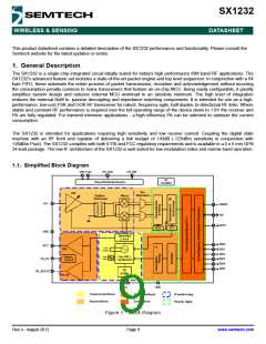
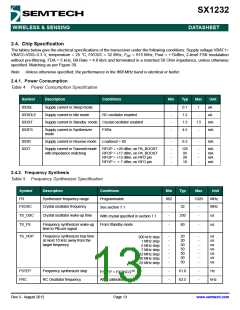
2.4. Chip Specification
DATASHEET
The tables below give the electrical specifications of the transceiver under the following conditions: Supply voltage VBAT1=
VBAT2=VDD=3.3 V, temperature = 25 °C, FXOSC = 32 MHz, F = 915 MHz, Pout = +13dBm, 2-level FSK modulation
RF
without pre-filtering, FDA = 5 kHz, Bit Rate = 4.8 kb/s and terminated in a matched 50 Ohm impedance, unless otherwise
specified. Matching as per Figure 39.
Note Unless otherwise specified, the performance in the 868 MHz band is identical or better.
2.4.1. Power Consumption
Table 4 Power Consumption Specification
Symbol
Description
Conditions
Min
Typ
Max
Unit
uA
IDDSL
IDDIDLE
IDDST
IDDFS
Supply current in Sleep mode
Supply current in Idle mode
-
-
-
-
0.1
1.2
1.3
4.5
1
-
RC oscillator enabled
uA
Supply current in Standby mode Crystal oscillator enabled
1.5
-
mA
mA
Supply current in Synthesizer
mode
FSRx
IDDR
IDDT
Supply current in Receive mode
LnaBoost = 00
-
9.3
-
mA
Supply current in Transmit mode
with impedance matching
RFOP = +20 dBm, on PA_BOOST
RFOP = +17 dBm, on PA_BOOST
RFOP = +13 dBm, on RFO pin
RFOP = + 7 dBm, on RFO pin
-
-
-
-
125
93
28
-
-
-
-
mA
mA
mA
mA
18
2.4.2. Frequency Synthesis
Table 5 Frequency Synthesizer Specification
Symbol
Description
Conditions
Min
Typ
Max
Unit
FR
Synthesizer frequency range
Crystal oscillator frequency
Programmable
See section 7.1
862
-
-
1020
-
MHz
MHz
FXOSC
32
TS_OSC
TS_FS
Crystal oscillator wake-up time
-
-
250
60
-
-
us
us
With crystal specified in section 7.1
From Standby mode
Frequency synthesizer wake-up
time to PllLock signal
TS_HOP
Frequency synthesizer hop time
at most 10 kHz away from the
target frequency
-
-
-
-
-
-
-
20
20
50
50
50
50
50
-
-
-
-
-
-
-
us
us
us
us
us
us
us
200 kHz step
1 MHz step
5 MHz step
7 MHz step
12 MHz step
20 MHz step
25 MHz step
FSTEP = FXOSC/219
After calibration
FSTEP
FRC
Frequency synthesizer step
RC Oscillator frequency
-
-
61.0
62.5
-
-
Hz
kHz
Rev 3 - August 2012
Page 13
www.semtech.com

 SEMTECH [ SEMTECH CORPORATION ]