LC89057W-VF4A-E
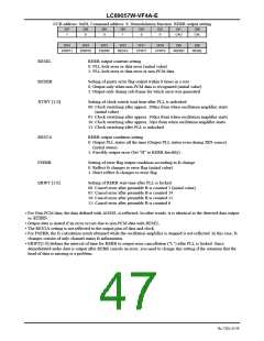
CCB address: 0xE8, Command address: 9; Demodulation function: RERR output setting
DI7
DI6
DI5
DI4
DI3
DI2
DI1
DI0
1
0
0
1
0
0
CAU
CAL
DI15
DI14
DI13
DI12
DI11
DI10
DI9
DI8
ERWT1
ERWT0
FSERR
RESTA
XTWT1
XTWT0
REDER
RESEL
RESEL
RERR output contents setting
0: PLL lock error or data error (initial value)
1: PLL lock error or data error or non-PCM data
REDER
Setting of parity error flag output within 8 times in a row
0: Output only when non-PCM data is recognized (initial value)
1: Output only during sub-frame for which error was generated
XTWT [1:0]
Setting of clock switch wait time after PLL is unlocked
00: Clock switching after approx. 200μs from when oscillation amplifier starts
(initial value)
01: Clock switching after approx. 100μs from when oscillation amplifier starts
10: Clock switching after approx. 50μs from when oscillation amplifier starts
11: Clock switching after PLL is unlocked
RESTA
RERR output condition setting
0: Output PLL status all the time (Output PLL status even during XIN source)
(initial status)
1: Forcibly output error (Set "H" to RERR forcibly)
FSERR
Setting of error flag output condition according to fs change
0: Reflect fs changes to error flag (initial value)
1: Don't reflect fs changes to error flag
ERWT [1:0]
Setting of RERR wait time after PLL is locked
00: Cancel error after preamble B is counted 3 (initial value)
01: Cancel error after preamble B is counted 24
10: Cancel error after preamble B is counted 12
11: Cancel error after preamble B is counted 6
•
For Non-PCM data, the data defined with AOSEL is reflected. In other words, it is identical to the detected data output
____________
to AUDIO.
•
•
•
Output data is muted if an error occurs due to non-PCM data with RESEL.
The RESTA setting is not reflected to the output pins of data and clock.
For FSERR, the fs calculation result obtained while the oscillation amplifier is stopped is not reflected. In this case, fs
changes consist of only channel status fs information.
•
ERWT[1:0] defines the interval of time for RERR to output error cancellation ("L") after PLL is locked. Since
demodulated audio data is output after RERR cancels an error, you need to change this setting if the situation that the
head of data is missing is a problem.
No.7202-47/59

 SANYO [ SANYO SEMICON DEVICE ]