LC89057W-VF4A-E
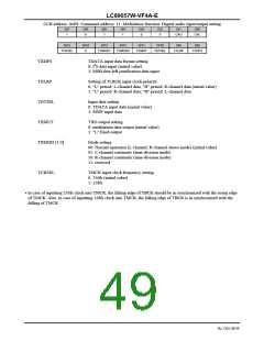
CCB address: 0xE8; Command address: 11; Modulation function: Digital audio input/output setting
DI7
DI6
DI5
DI4
DI3
DI2
DI1
DI0
1
0
1
1
0
0
CAU
CAL
DI15
DI14
0
DI13
DI12
DI11
DI10
DI9
DI8
TCKSEL
TXMOD1
TXMOD0
TXMUT
TDTSEL
TXLRP
TXDFS
TXDFS
TXLRP
TDTSEL
TXMUT
TDATA input data format setting
0: I2S data input (initial value)
1: MSB-first left-justification data input
Setting of TLRCK input clock polarity
0: "L" period: L-channel data; "H" period: R-channel data (initial value)
1: "L" period: R-channel data; "H" period: L-channel data
Input data setting
0: TDATA input data (initial value)
1: SDIN input data
TXO output setting
0: modulation data output (initial value)
1: "L" fixed output
TXMOD [1:0]
TCKSEL
Mode setting
00: Normal operation (L-channel, R-channel stereo mode) (initial value)
01: L-channel continuity (time-division mode)
10: R-channel continuity (time-division mode)
11: reserved
TMCK input clock frequency setting
0: 256fs (initial value)
1: 128fs
•
In case of inputting 256fs clock into TMCK, the falling edge of TBCK should be in synchronized with the rising edge
of TMCK. Also, in case of inputting 128fs clock into TMCK, the falling edge of TBCK is in synchronized with the
falling of TMCK.
No.7202-49/59

 SANYO [ SANYO SEMICON DEVICE ]