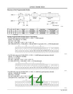
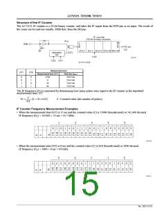
LC72121, 72121M, 72121V
Other Items
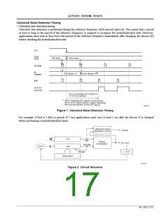
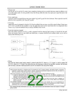
• Notes on the phase comparator dead zone
DZ1
0
DZ0
0
Dead zone mode
Charge pump
ON/ON
Dead zone
– –0s
–0s
DZA
DZB
DZC
DZD
0
1
ON/ON
1
0
OFF/OFF
OFF/OFF
+0s
1
1
+ +0s
When the charge pump is used with one of the ON/ON modes, correction pulses are generated from the charge pump
even if the PLL is locked. As a result, it is easy for the loop to become unstable, and special care is required in
application design. The following problems can occur if an ON/ON mode is used.
— Sidebands may be created by reference frequency leakage.
— Sidebands may be created by low-frequency leakage due to the correction pulse envelope.
Although the loop is more stable when a dead zone is present (i.e. when an OFF/OFF mode is used), a dead zone
makes it more difficult to achieve excellent C/N characteristics. On the other hand, while it is easy to achieve good C/N
characteristics when there is no dead zone, achieving good loop stability is difficult. Accordingly, the DZA and DZB
settings, in which there is no dead zone, can be effective in situations where a signal-to-noise ratio of 90 to 100 dB or
higher is required in FM reception, or where it is desirable to increase the pilot margin in AM stereo reception.
However, if such a high signal-to-noise ratio is not required for FM reception, if an adequate pilot margin can be
acquired in AM stereo reception, or if AM stereo is not required, then either DZC or DZD, in which there is a dead
zone, should be chosen.
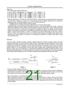
Dead Zone
As shown in figure 1, the phase comparator compares a reference frequency (fr) with fp. As shown in figure 2, the phase
comparator's characteristics consist of an output voltage (V) that is proportional to the phase difference ø. However, due
to internal circuit delay and other factors, an actual circuit has a region (the dead zone, B) where the circuit cannot
actually compare the phases. To implement a receiver with a high S/N ratio, it is desirable that this region be as small as
possible. However, it is often desirable to have the dead zone be slightly wider in popularly-priced models. This is
because in certain cases, such as when there is a strong RF input, popularly-priced models can suffer from mixer to VCO
RF leakage that modulates the VCO. When the dead zone is small, the circuit outputs signals to correct this modulation
and this output further modulates the VCO. This further modulation may then generate beats and the RF signal.
Figure 1
Figure 2
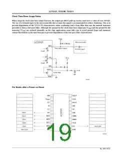
• Notes on the FMIN, AMIN, and IFIN pins
Coupling capacitors should be placed as close to their pin as possible. A capacitance of about 100 pF is desirable for
these capacitors. In particular, if the IFIN pin coupling capacitor is not held under 1000 pF, the time to reach the bias
level may become excessive and incorrect counts may result due to the relationship with the wait time.
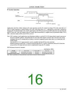
• Notes on IF counting → Use the SD signal in conjunction with IF counting
When counting the IF frequency, the microcontroller must determine the presence or absence of the IF IC SD (station
detect) signal and turn on the IF counter buffer output and execute the IF count only if there is an SD signal. Auto-
search techniques that only use the IF counter are subject to incorrect stopping at points where there is no station due to
IF buffer leakage.
No. 5815-21/22

 SANYO [ SANYO SEMICON DEVICE ]