LC72121, 72121M, 72121V
Continued from preceding page.
No.
4
Control block/data
Function
Related data
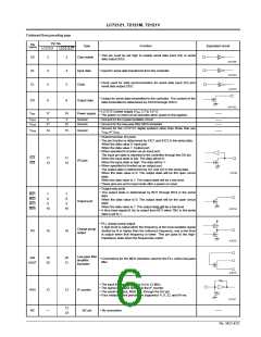
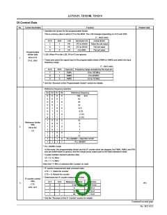
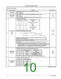
• Specifies input or output for the shared function I/O pins (IO1 and IO2).
I/O port setup data
IOC1,IOC2
Data = 0: Input port
Data = 1: Output port
• Determines the output state of the BO1 through BO4, IO1, and IO2 output ports.
Data = 0: Open
Data = 1: Low level
Output port data
BO1 to BO4
IO1,IO2
IOC1
IOC2
5
• The data is reset to 0, setting the pins to the open state, after a power on reset.
• Determines the DO pin output.
DOC2
DOC1
DOC0
DO pin state
Open
0
0
0
0
1
1
1
1
0
0
1
1
0
0
1
1
0
1
0
1
0
1
0
1
Low when the PLL is unlocked
end-UC *1
Open
Open
The IO1 pin state *2
The IO2 pin state *2
Open
UL0, UL1
CTE
The open state is selected after a power on reset.
*1. end-UC: IF counter measurement end check
DO pin control data
DOC0
6
DOC1
IOC1
IOC2
DOC2
(1)When end-UC is selected and an IF count is started (by switching CTE from 0 to 1), the DO pin
automatically goes to the open state.
(2)When the IF counter measurement period completes, the DO pin goes to the low level, allowing
applications to test for the completion of the count period.
(3)The DO pin is set to the open state by performing a serial data input or output operation (when the CE
pin is set high).
*2. The DO pin will go to the open state if the corresponding IO pin is set up to be an output port.
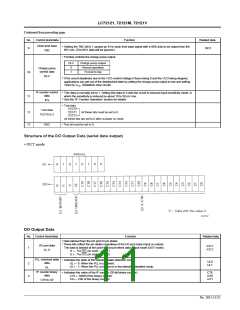
Note: During the data input period (the period that CE is high in IN1 or IN2 mode), the DO pin goes to the
open state regardless of the DO pin control data (DOC0 to DOC2). During the data output period (the
period that CE is high in OUT mode) the DO pin state reflects the internal DO serial data in
synchronization with the CL clock, regardless of the DO pin control data (DOC0 to DOC2).
• Selects the width of the phase error (øE) detected for PLL lock state discrimination. The state is taken to
be unlocked if a phase error in excess of the detection width occurs.
UL1
0
UL0
0
øE detection width
Stopped
0
Detection output
Open
DOC0
DOC1
DOC2
Unlocked state
detection data
7
0
1
øE is output directly
øE is extended by 1 to 2 ms
øE is extended by 1 to 2 ms
UL0, UL1
1
0
±0.55 µs
±1.11 µs
1
1
* When the PLL is unlocked, the DO pin goes low and UL in the serial data output is set to 0.
• Controls the phase comparator dead zone
DZ1
0
DZ
0
Dead zone mode
DZA
DZB
DZC
DZD
Phase comparator
control data
8
0
1
DZ0, DZ1
1
0
1
1
Dead zone width: DZA < DZB < DZC < DZD
Continued on next page.
No. 5815-10/22

 SANYO [ SANYO SEMICON DEVICE ]