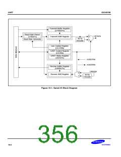
UART
S3C4510B
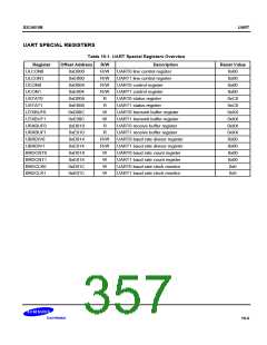
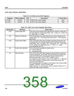
UART CONTROL REGISTERS
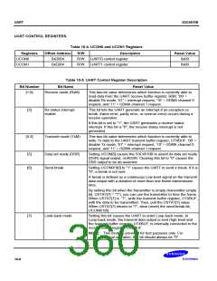
Table 10-4. UCON0 and UCON1 Registers
Registers
UCON0
UCON1
Offset Address
0xD004
R/W
R/W
R/W
Description
UART0 control register
UART1 control register
Reset Value
0x00
0xE004
0x00
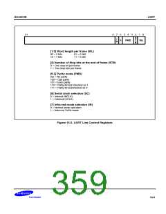
Table 10-5. UART Control Register Description
Bit Name Reset Value
Bit Number
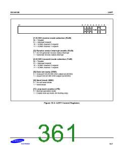
[1:0]
Receive mode (RxM)
This two-bit value determines which function is currently able to
read data from the UART receive buffer register, RBR: '00' =
disable Rx mode, '01' = interrupt request, '10' = GDMA channel 0
request, and '11' = GDMA channel 1 request.
[2]
Rx status interrupt
enable
This bit lets the UART generate an interrupt if an exception (a
break, frame error, parity error, or overrun error) occurs during a
receive operation.
If this bit is set to "1", the UART generates a receive status
interrupt. If this bit is "0", the receive status interrupt is not
generated.
[4:3]
Transmit mode (TxM)
This two-bit value determines which function is currently able to
write Tx data to the UART transmit buffer register, UTXBUF. '00' =
disable Tx mode, '01' = interrupt request, '10' = GDMA channel 0
request, and '11' = GDMA channel 1 request.
[5]
[6]
Data set ready (DSR)
Send break
Setting UCON[5] causes the S3C4510B to assert its data set ready
(DSR) signal output, nUADSR. Clearing this bit to "0" causes the
DSR output to be de-asserted.
Setting UCON0/1[6] to "1" causes the UART to send a break. If it is
"0", a break is not sent.
A break is defined as a continuous Low level signal on the transmit
data output with a duration of more than one frame transmission
time.
By setting this bit when the transmitter is empty (transmitter empty
bit, USTAT[7] = "1"), you can use the transmitter to time the frame.
When USTAT[7] is "1", write the transmit buffer register, UTXBUF,
with the data to be transmitted. Then, poll the USTAT[7] value.
When USTAT[7] returns to "1", clear (reset) the send break bit,
UCON0/1[6].
[7]
Look-back mode
Setting this bit causes the UART to enter Loop-back mode. In
Loop-back mode, the transmit data output is sent High level and
the transmit buffer register, UTXBUF, is internally connected to the
receive buffer register, URXBUF.
NOTE: This mode is provided for test purposes only. For
normal operation, this bit should always be "0".
10-6

 SAMSUNG [ SAMSUNG ]