UART
S3C4510B
UART LINE CONTROL REGISTERS
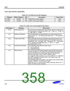
Table 10-2. ULCON0 and ULCON1 Registers
Registers
ULCON0
Offset Address
0xD000
R/W
R/W
R/W
Description
UART0 line control register
UART1 line control register
Reset Value
0x00
ULCON1
0xE000
0x00
Table 10-3. UART Line Control Register Description
Bit Number
Bit Name
Reset Value
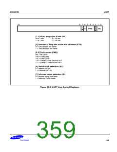
[1:0]
World length (WL)
This two-bit word length value indicates the number of data bits to
be transmitted or received per frame: ’00’ = 5 bits, ’01’ = 6 bits, '10'
= 7 bits, and ’11’ = 8 bits.
[2]
Number of Stop bits
Parity mode (PMD)
This bit specifies how many Stop bits are used to signal end-of-
frame (EOF): "0" = one Stop bit per frame and "1" = two Stop bits
per frame.
[5:3]
The 3-bit parity mode value specifies how parity generation and
checking are to be performed during UART transmit and receive
operations: '0xx' = no parity, ’100’ = odd parity, ’101’ = even parity,
'110' = parity is forced/checked as a "1", and '111' = parity
forced/checked as a "0".
[6]
[7]
Serial Clock Selection
Infra-red mode
This selection bit specifies the clock source.
0 = Internal (MCLK)
1 = External (UCLK)
The S3C4510B UART block supports infra-red (IR) transmit and
receive operations. In IR mode, the transmit period is pulsed at a
rate of 3/16 that of the normal serial transmit rate (when the
transmit data value in the UTXBUF register is zero).
To enable IR mode operation, you set ULCON[7] to "1". Otherwise,
the UART operates in normal mode. In IR receive mode, the
receiver must detect the
3/16 pulsed period to recognize a zero value in the receiver buffer
register, URXBUF, as the IR receive data.
When bit [7] is "0", normal UART mode is selected. When it is "1",
infra-red Tx/Rx mode is selected.
10-4

 SAMSUNG [ SAMSUNG ]