HDLC CONTROLLERS
S3C4510B
In the NRZ/NRZI mode, the DPLL source clock must be 32 times the data rates. In this mode, the transmit and
receive clock outputs of the DPLL are identical, and the clocks are phased so that the receiver samples the data
in the middle of the bit cell.
The DPLL counts the 32x clock using an internal 5-bit counter. As the 32x clock is counted, the DPLL searches
the incoming data stream for edges (either positive or negative transition). The output of DPLL is High while the
DPLL is waiting for an edge in the incoming data stream. When it detects a transition, the DPLL starts the clock
recovery operation.
The first sampling edge of the DPLL occurs at the counter value of 16 after the first edge is detected in the
incoming data stream. The second sampling edge occurs following the next 16. When the transition of incoming
data occurs at a count value other than 16, the DPLL adjusts its clock outputs during the next 0 to 31 counting
cycle by extending or shortening its count by one, which effectively moves the edge of the clock sampling the
receive data closer to the center of the bit cell.
The adding or subtracting of a count of 1 will produce a phase jitter of 5.63 degrees on the output. Because the
DPLL uses both edges of the incoming signal for its clock source comparison, the mark-space ratio (50%) of the
incoming signal must not deviate more than 1.5% of its baud rate if proper locking is to occur.
In the FM mode, the DPLL clock must be 16 times the data rate. The 5-bit counter in the DPLL counts from 0 to
31, so the DPLL makes two sampling clocks during the 0 to 31 counting cycle. The DPLL output is Low while the
DPLL is waiting for an edge in the incoming data stream. The first edge the DPLL detects is assumed to be a
valid clock edge. From this point, the DPLL begins to generate output clocks.
In this mode, the transmit clock output of the DPLL lags the receive clock outputs by 90 degrees to make the
transmit and receive bit cell boundaries the same, because the receiver must sample the FM data at a one-
quarter and three-quarters bit time.
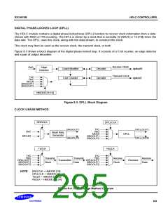
You can program the 32X clock for the DPLL to originate from one of the RxC input pins, from the TxC pin, or
from the baud rate generator output. You can also program the DPLL output to be "echoed out" of the HDLC
module over the TXC pin(if the TXC pin is not being used as an input).
During idle time, you can set the TxPRMB in HCON to send the special pattern required for a remote DPLL to
lock the phase. In this case, the content of the HPRMB register is sent repeatedly. The length of preamble is
determined by TxPL bit in HMODE[10:8].
It is noticed that the frequency of the receive clock (RxC) should be slower than half of the internal system clock
i.e., MCLK/2. Otherwise, the data transfer from receive FIFO to memory could be lost.
8-10

 SAMSUNG [ SAMSUNG ]