S3C4510B
HDLC CONTROLLERS
FIFO STRUCTURE
In both transmit and receive directions, 32-byte (8 word) deep FIFOs are provided for the intermediate storage of
data between the serial interface and the CPU Interface.
TWO-CHANNEL DMA ENGINE
The HDLC module has a two-channel DMA engine for Tx/Rx FIFOs. The DMA Tx channel programming and the
RX channel programming are described in the transmitter and receiver operation sections, respectively.
BAUD RATE GENERATOR
The HDLC module contains a programmable baud rate generator(BRG). The BRG register contains a 16-bit time
constant register, a 12-bit down counter for time constant value, two control bit to divide 16, and another two
control bits to divide 16 or 32.
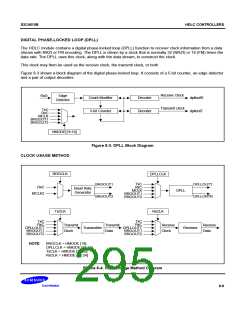
A clock diagram of the BRG is shown in Figure 8-2.
At a start-up, the flip-flop on the output is set in a High state, the value in the time constant register is loaded into
the counter, and the counter starts counting down. The output of the baud rate generator may toggle upon
reaching zero, the value in the time constant register is loaded into the counter, and the process is repeated. The
time constant may be changed any time, but the new value does not take effect until the next load of the counter.
The output of the baud rate generator may be used as either the transmit clock, the receive clock, or both. It can
also drive the digital phase-locked loop. If the receive or transmit clock is not programmed to come from the TXC
pin, the output of the baud rate generator may be echoed out via the TXC pin.
The following formula relates the time constant to the baud rate where MCLK2 or RXC is the baud rate generator
input frequency in Hz. BRG generates 2 output signals, BRGOUT1, BRGOUT2, for transmit/receive clocks and
the DPLL input clock.
BRGOUT1 = (MCLK2 or RXC) / (CNT0 + 1) / (16CNT1
BRGOUT2 = BRGOUT1 / (1 or 16 or 32 according to CNT2 value of the HBRGTC)
)
CNT0
CNT1
CNT2
RxC
BRGOUT2
BRGOUT1
Divide by
1 or 16
Divide by
1 or 16 or 32
12-bit counter
MCLK2
CNT0: HBRGTC [15:4]
CNT1: HBRGTC [3:2]
CNT2: HBRGTC [1:0]
BRGCLK: HMODE [19]
BRGCLK
Figure 8-2. Baud Rate Generator Block Diagram
8-7

 SAMSUNG [ SAMSUNG ]