S3C4510B
HDLC CONTROLLERS
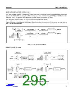
DIGITAL PHASE-LOCKED LOOP (DPLL)
The HDLC module contains a digital phase-locked loop (DPLL) function to recover clock information from a data
stream with NRZI or FM encoding. The DPLL is driven by a clock that is normally 32 (NRZI) or 16 (FM) times the
data rate. The DPLL uses this clock, along with the data stream, to construct the clock.
This clock may then be used as the receive clock, the transmit clock, or both.
Figure 8-3 shows a block diagram of the digital phase-locked loop. It consists of a 5-bit counter, an edge detector
and a pair of output decoders.
Receive Clock
Transmit clock
RxD
Edge
Detector
Count Modifier
5-bit Counter
Decoder
Decoder
dplloutR
dplloutT
TxC
RxC
MCLK
BRGOUT1
BRGOUT2
HMODE[18:16]
Figure 8-3. DPLL Block Diagram
CLOCK USAGE METHOD
BRGCLK
DPLLCLK
TxC
RxC
BRGOUT1
BRGOUT2
DPLLOUTT
RxC
Baud Rate
Generator
DPLL
MCLK
MCLK2
BRGOUT1
BRGOUT2
DPLLORTR
TxCLK
RxCLK
TxC
TxC
RxC
DPLLOUTT
BRGOUT1
BRGOUT2
RxC
DPLLOUTT
BRGOUT1
BRGOUT2
Transmit
Transmit
Receive
Clock
Receive
Data
Transmitter
Receiver
Clock
Data
NOTE:
BRGCLK = HMODE [19]
DPLLCLK = HMODE [18:16]
TxCLK = HMODE [22:20]
RxCLK = HMODE [26:24]
Figure 8-4. Clock Usage Method Diagram
8-9

 SAMSUNG [ SAMSUNG ]