HDLC CONTROLLERS
S3C4510B
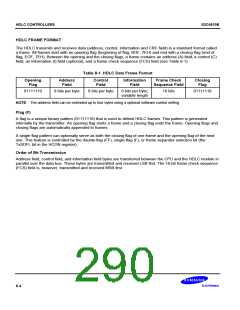
HDLC FRAME FORMAT
The HDLC transmits and receives data (address, control, information and CRC field) in a standard format called
a frame. All frames start with an opening flag (beginning of flag, BOF, 7EH) and end with a closing flag (end of
flag, EOF, 7EH). Between the opening and the closing flags, a frame contains an address (A) field, a control (C)
field, an information (I) field (optional), and a frame check sequence (FCS) field (see Table 8-1).
Table 8-1. HDLC Data Frame Format
Opening
Flag
Address
Field
Control
Field
Information
Field
Frame Check
Sequence Field
Closing
Flag
01111110
8 bits per byte
8 bits per byte
8 bits per byte;
variable length
16 bits
01111110
NOTE: The address field can be extended up to four bytes using a optional software control setting.
Flag (F)
A flag is a unique binary pattern (01111110) that is used to delimit HDLC frames. This pattern is generated
internally by the transmitter. An opening flag starts a frame and a closing flag ends the frame. Opening flags and
closing flags are automatically appended to frames.
A single flag pattern can optionally serve as both the closing flag of one frame and the opening flag of the next
one. This feature is controlled by the double-flag (FF), single-flag (F), or frame separator selection bit (the
TxSDFL bit in the HCON register).
Order of Bit Transmission
Address field, control field, and information field bytes are transferred between the CPU and the HDLC module in
parallel over the data bus. These bytes are transmitted and received LSB first. The 16-bit frame check sequence
(FCS) field is, however, transmitted and received MSB first.
8-4

 SAMSUNG [ SAMSUNG ]