2
I C BUS CONTROLLER
S3C4510B
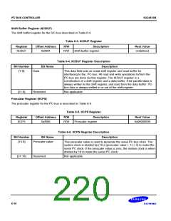
Data Transfer Format
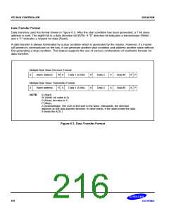
Data transfers uses the format shown in Figure 6-3. After the start condition has been generated, a 7-bit slave
address is sent. The eighth bit is a data direction bit (R/W). A "0" direction bit indicates a transmission (Write)
and a "1" indicates a request for data (Read).
A data transfer is always terminated by a stop condition which is generated by the master. However, if a master
still wishes to communicate on the bus, it can generate another start condition and address another slave without
first generating a stop condition. This feature supports the use of various combinations of read/write formats for
data transfers.
Multiple Byte Slave Receiver Format:
S
Slave address
W A
Data 1 (8 bits)
A
A
Data 2
Data 2
A
A
Data M
Data M
A P
A P
Multiple Byte Slave Transmitter Format:
Slave address R A Data 1 (8 bits)
S
NOTE:
S (Start)
W (Write; bit value is 0)
R (Read; bit value is 1)
P (Stop),
A (Acknowledge; The ACK is first sent to the slave. Afterwards, the direction
depends on the data transfer direction. In other words, if the mater reads the data,
it sends the ACK.)
Figure 6-3. Data Transfer Format
6-6

 SAMSUNG [ SAMSUNG ]