2
I C BUS CONTROLLER
S3C4510B
FUNCTIONAL DESCRIPTION
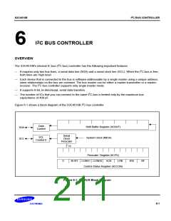
The S3C4510B I2C bus controller is the master of the serial I2C-bus. Using a prescaler register, you can program
the serial clock frequency that is supplied to the I2C bus controller. The serial clock frequency is calculated as
follows:
MCLK / (16 ´ (prescaler register value + 1) + 3)
To initialize the serial I2C-bus, the programmer sends a start code by writing "01" to bits [5:4]of the control status
register, IICCON. The bus controller then sends the 7-bit slave address and a read/write control bit through shift
buffer register. The receiver sends an acknowledge by pulling the SDA line from high to low during a master SCL
pulse.
To continue the data write operation, you must set the BF bit in the control status register and then write the data
to the shift buffer register. Whenever the shift buffer register is read or written, the BF bit is cleared
automatically. For the consecutive read/write operations, you must set the ACK bit in the control status register.
For read operations, you can read the data after you have set the BF bit in the control status register. To signal
the end of the read operation, you can reset the ACK bit to inform the receiver/transmitter when the last byte is to
be written/read.
Following a read/write operation, you set IICCON[5:4] to "10" to generate a stop code. If you want to complete
another data transfer before issuing the Stop code, you can send the start code using the repeat start command
(with IICCON[5:4] = "11"). When the slave address and read/write control bit have been sent, and when the
receive acknowledge has been issued to control SCL timing, the data transfer is initiated.
6-2

 SAMSUNG [ SAMSUNG ]