K9F5608U0B-VCB0,VIB0,FCB0,FIB0
K9F5608Q0B-DCB0,DIB0,HCB0,HIB0
K9F5608U0B-YCB0,YIB0,PCB0,PIB0
K9F5608U0B-DCB0,DIB0,HCB0,HIB0
K9F5616Q0B-DCB0,DIB0,HCB0,HIB0
K9F5616U0B-YCB0,YIB0,PCB0,PIB0
K9F5616U0B-DCB0,DIB0,HCB0,HIB0
FLASH MEMORY
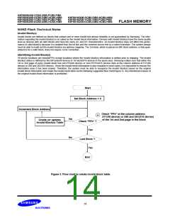
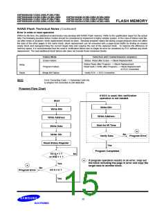
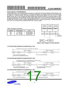
Pointer Operation of K9F5608X0B(X8)
Samsung NAND Flash has three address pointer commands as a substitute for the two most significant column addresses. ’00h’
command sets the pointer to ’A’ area(0~255byte), ’01h’ command sets the pointer to ’B’ area(256~511byte), and ’50h’ command sets
the pointer to ’C’ area(512~527byte). With these commands, the starting column address can be set to any of a whole
page(0~527byte). ’00h’ or ’50h’ is sustained until another address pointer command is inputted. ’01h’ command, however, is effec-
tive only for one operation. After any operation of Read, Program, Erase, Reset, Power_Up is executed once with ’01h’ command,
the address pointer returns to ’A’ area by itself. To program data starting from ’A’ or ’C’ area, ’00h’ or ’50h’ command must be input-
ted before ’80h’ command is written. A complete read operation prior to ’80h’ command is not necessary. To program data starting
from ’B’ area, ’01h’ command must be inputted right before ’80h’ command is written.
"A" area
"B" area
"C" area
(00h plane)
(01h plane)
(50h plane)
256 Byte
256 Byte
16 Byte
Table 2. Destination of the pointer
Command
Pointer position
Area
00h
01h
50h
0 ~ 255 byte
256 ~ 511 byte
512 ~ 527 byte
1st half array(A)
2nd half array(B)
spare array(C)
"A"
"B"
"C"
Internal
Page Register
Pointer select
commnad
(00h, 01h, 50h)
Pointer
Figure 4. Block Diagram of Pointer Operation
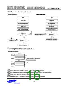
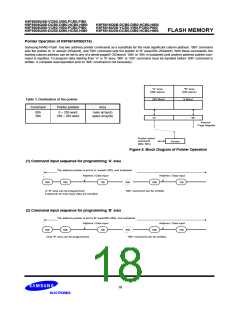
(1) Command input sequence for programming ’A’ area
The address pointer is set to ’A’ area(0~255), and sustained
Address / Data input
Address / Data input
00h
80h
10h
00h
80h
10h
’A’,’B’,’C’ area can be programmed.
’00h’ command can be omitted.
It depends on how many data are inputted.
(2) Command input sequence for programming ’B’ area
The address pointer is set to ’B’ area(256~512), and will be reset to
’A’ area after every program operation is executed.
Address / Data input
Address / Data input
80h 10h
01h
80h
10h
01h
’B’, ’C’ area can be programmed.
It depends on how many data are inputted.
’01h’ command must be rewritten before
every program operation
(3) Command input sequence for programming ’C’ area
The address pointer is set to ’C’ area(512~527), and sustained
Address / Data input
Address / Data input
80h 10h
50h
80h
10h
50h
Only ’C’ area can be programmed.
’50h’ command can be omitted.
17

 SAMSUNG [ SAMSUNG ]