BD9415FS
3.3. DCDC Parts Selection
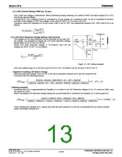
3.3.1. OCP Setting / Calculation Method for the Current Rating of DCDC Parts
OCP detection stops the switching when the CS pin voltage is more than 0.45V(Typ). The resistor value of CS pin, RCS
needs to be considered by the coil L current. And the current rating of DCDC external parts is required more than the
peak current of the coil.
Shown below are the calculation method of the coil peak current, the selection method of Rcs (the resistor value of CS
pin) and the current rating of the external DCDC parts at Continuous Current Mode.
(The calculation method of the coil peak current, IPEAK at Continuous Current Mode)
At first, since the ripple voltage at CS pin depends on the application
condition of DCDC, the following variables are used.
Vout voltage = VOUT [V]
LED total current = IOUT [A]
L
VOUT
DCDC input voltage of the power stage = VIN [V]
Efficiency of DCDC =η [%]
VIN
IL
And then, the average input current IIN is calculated by the following
equation.
fsw
VOUT [V ] IOUT [A]
IIN
[A]ꢀ
VIN [V ][%]
GATE
And the ripple current of the inductor L (ΔIL[A]) can be calculated by
CS
using DCDC the switching frequency, fSW, as follows.
Rcs
GND
(VOUT [V ]VIN [V]) VIN [V ]
L[H]VOUT [V] fSW [Hz]
IL
[A]ꢀ
(V)
On the other hand, the peak current of the inductor IPEAK can be expressed
as follows.
IL[A]
… (1)
IPEAK IIN [A]
[A]ꢀ
2
Therefore, the bottom of the ripple current IMIN is
(A)
(t)
IL[A]
Imin IIN [A]
ꢀ
or 0
Ipeak
2
ΔIL
IIN
If IMIN>0, the operation mode is CCM (Continuous Current Mode),
otherwise the mode is DCM (Discontinuous Current Mode).
Imin
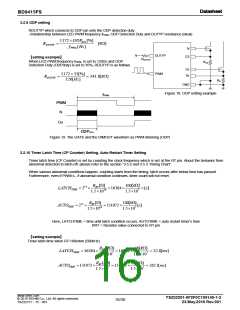
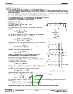
(The selection method of RCS at Continuous Current Mode)
IPEAK flows into RCS and that causes the voltage signal to CS pin. (Please
refer to the timing chart at the right)
(t)
(V)
Peak voltage VCSPEAK is as follows.
0.4V
0.45V
VCSPEAK RCS IPEAK [V]ꢀ
VCSpeak
As this VCSPEAK reaches 0.4V (typical), the DCDC output stops the
switching.
Therefore, RCS value is necessary to meet the condition below.
(t)
RCS IPEAK [V] 0.45[V]ꢀ
Figure 20. Coil Current Waveform
(The current rating of the external DCDC parts)
The peak current as the CS voltage reaches OCP level (0.4V (Typ)) is defined as IPEAK_DET
.
0.45[V ]
RCS []
… (2)
IPEAK _ DET
[A]ꢀ
The relationship among IPEAK (equation (1)), IPEAK_DET (equation (2)) and the current rating of parts is required to meet
the following
I
I
The current rating of parts
peak
peak _det
Please make the selection of the external parts such as FET, Inductor, diode meet the above condition.
www.rohm.com
TSZ02201-0F2F0C100140-1-2
23.May.2016 Rev.001
© 2015 ROHM Co., Ltd. All rights reserved.
17/30
TSZ22111・15・001

 ROHM [ ROHM ]