BD9415FS
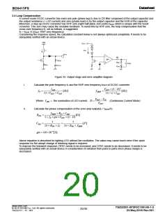
3.4 Loop Compensation
A current mode DCDC converter has each one pole (phase lag) fP due to CR filter composed of the output capacitor and
the output resistance (= LED current) and zero (phase lead) fZ by the output capacitor and the ESR of the capacitor.
Moreover, a step-up DCDC converter has RHP zero (right-half plane zero point) fZRHP which is unique with the boost
converter. This zero may cause the unstable feedback. To avoid this by RHP zero, the loop compensation that the
cross-over frequency fc, set as follows, is suggested.
fc = fZRHP /5 (fZRHP: RHP zero frequency)
Considering the response speed, the calculated constant below is not always optimized completely. It needs to be
adequately verified with an actual device.
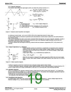
VIN
VOUT
L
ILED
VOUT
-
+
FB
gm
RESR
COUT
RFB1
CFB1
CFB2
RCS
Figure 23. Output stage and error amplifier diagram
i.
Calculate the pole frequency fP and the RHP zero frequency fZRHP of DC/DC converter
VOUT (1 D)2
2 L ILED
ILED
fP
[Hz]
fZRHP
[Hz]
2 VOUT COUT
VOUT VIN
ILED
the summation of LED current, D
Where
(Continuous Current Mode)
VOUT
ii.
Calculate the phase compensation of the error amp output(fc = fZRHP/5)
fRHZP RCS ILED
5 fP gm VOUT (1 D)
RFB1
[]
1
5
CFB1
[F]
2 RFB1 fC 2 RFB! fZRHP
gm 4.0104[S]
Above equation is described for lighting LED without the oscillation. The value may cause much error if the quick
response for the abrupt change of dimming signal is required.
To improve the transient response, RFB1 needs to be increased, and CFB1 needs to be decreased. It needs to be
adequately verified with an actual device in consideration of variation from parts to parts since phase margin is
decreased.
www.rohm.com
TSZ02201-0F2F0C100140-1-2
23.May.2016 Rev.001
© 2015 ROHM Co., Ltd. All rights reserved.
20/30
TSZ22111・15・001

 ROHM [ ROHM ]