BD9415FS
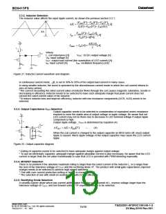
3.3.2. Inductor Selection
The inductor value affects the input ripple current, as shown the previous section 3.3.1.
(VOUT [V ]VIN [V ])VIN [V]
L[H]VOUT [V ] fSW[Hz]
IL
[A]ꢀ
ΔIL
VOUT [V ] IOUT [A]
[A]ꢀ
IIN
VIN [V ][%]
VIN
IL[A]
IPEAK IIN [A]
[A]ꢀ
2
IL
L
Where
VOUT
L: coil inductance [H]
VIN: input voltage [V]
VOUT: DCDC output voltage [V]
IOUT: output load current (the summation of LED current) [A]
IIN: input current [A] fSW: oscillation frequency [Hz]
RCS
COUT
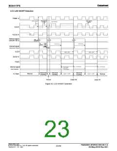
Figure 21. Inductor current waveform and diagram
In continuous current mode, ⊿IL is set to 30% to 50% of the output load current in many cases.
In using smaller inductor, the boost is operated by the discontinuous current mode in which the coil current returns to
zero at every period.
*The current exceeding the rated current value of inductor flown through the coil causes magnetic saturation, results in
decreasing in efficiency. Inductor needs to be selected to have such adequate margin that peak current does not
exceed the rated current value of the inductor.
*To reduce inductor loss and improve efficiency, inductor with low resistance components (DCR, ACR) needs to be
selected.
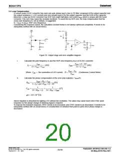
3.3.3. Output Capacitance COUT Selection
Output capacitor needs to be selected in consideration of equivalent series resistance
required to even the stable area of output voltage or ripple voltage. Be aware that set
VIN
LED current may not be flown due to decrease in LED terminal voltage if output ripple
component is high.
Output ripple voltage _VOUT is determined by Equation (4):
IL
L
VOUT
VOUT ILRESR[V]ꢀ
(4)
RESR
COUT
When the coil current is charged to the output capacitor as MOS turns off, much output
ripple is caused. Much ripple voltage of the output capacitor may cause the LED current
ripple.
RCS
Figure 22. Output capacitor diagram
* Rating of capacitor needs to be selected to have adequate margin against output voltage.
* To use an electrolytic capacitor, adequate margin against allowable current is also necessary. Be aware that the LED
current is larger than the set value transitionally in case that LED is provided with PWM dimming especially.
3.3.4. MOSFET Selection
There is no problem if the absolute maximum rating is larger than the rated current of the inductor L, or is larger than
the sum of the tolerance voltage of COUT and the rectifying diode VF. The product with small gate capacitance (injected
charge) needs to be selected to achieve high-speed switching.
* One with over current protection setting or higher is recommended.
* The selection of one with small on resistance results in high efficiency.
3.3.5. Rectifying Diode Selection
A schottky barrier diode which has current ability higher than the rated current of L, reverse voltage larger than the
tolerance voltage of COUT, and low forward voltage VF especially needs to be selected.
www.rohm.com
TSZ02201-0F2F0C100140-1-2
© 2015 ROHM Co., Ltd. All rights reserved.
19/30
23.May.2016 Rev.001
TSZ22111・15・001

 ROHM [ ROHM ]