Daattaasshheeeett
BD7xxL5FP-C
●Selection of Components Externally Connected
・VCC pin
Insert capacitors with a capacitance of 0.1μF or higher between the VCC and GND pin. Choose the capacitance
according to the line between the power smoothing circuit and the VCC pin. Selection of the capacitance also
depends on the application. Verify the application and allow for sufficient margins in the design. We recommend
using a capacitor with excellent voltage and temperature characteristics.
・Output pin capacitor
In order to prevent oscillation, a capacitor needs to be placed between the output pin and GND pin. We recommend
using a capacitor with a capacitance of 4.7μF or higher. Electrolytic, tantalum and ceramic capacitors can be used.
When selecting the capacitor ensure that the capacitance of 4.7μF or higher is maintained at the intended applied
voltage and temperature range. Due to changes in temperature the capacitor’s capacitance can fluctuate possibly
resulting in oscillation. For selection of the capacitor refer to the IOUT vs. ESR data. The stable operation range
given in the reference data is based on the standalone IC and resistive load. For actual applications the stable
operating range is influenced by the PCB impedance, input supply impedance and load impedance. Therefore
verification of the final operating environment is needed.
When selecting a ceramic type capacitor, we recommend using X5R, X7R or better with excellent temperature and
DC-biasing characteristics and high voltage tolerance.
Also, in case of rapidly changing input voltage and load current, select the capacitance in accordance with verifying
that the actual application meets with the required specification.
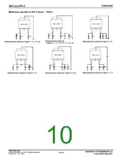
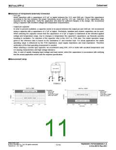
●Measurement setup
TO252-3
○Condition
VCC=13.5V
Cin=0.1µF
4.7µF<COUT<22µF
-40℃<Ta<+125℃
○Condition
VCC=13.5V
Cin=0.1µF
4.7µF<COUT<100µF
-40℃<Ta<+125℃
www.rohm.com
© 2012 ROHM Co., Ltd. All rights reserved.
TSZ22111・15・001
TSZ02201-T2T0AN00020-1-2
2.Oct.2012 Rev.001
11/18

 ROHM [ ROHM ]