Data Sheet
AD7656-1/AD7657-1/AD7658-1
APPLICATION HINTS
and each REFCAPx pin. Avoid sharing these capacitors between
pins, and use vias to connect the capacitors to the power and
ground planes. In addition, use wide, short traces between each
via and the capacitor pad, or place the vias adjacent to the capacitor
pad to minimize parasitic inductances. The AD7656-1/AD7657-1/
AD7658-1 offer the user a reduced decoupling solution that is pin
and software compatible with AD7656/AD7657/AD7658. The
recommended reduced decoupling required for AD7656-1/
AD7657-1/AD7658-1 is outlined in Figure 28.
LAYOUT
Design the printed circuit board (PCB) that houses the AD7656-1/
AD7657-1/AD7658-1 so that the analog and digital sections are
separated and confined to different areas of the board.
Use at least one ground plane. It can be common or split
between the digital and analog sections. In the case of the split
plane, join the digital and analog ground in only one place,
preferably underneath the AD7656-1/AD7657-1/AD7658-1,
or at least as close as possible to the part.
POWER SUPPLY CONFIGURATION
If the AD7656-1/AD7657-1/AD7658-1 are in a system where
multiple devices require analog-to-digital ground connections,
the connection should still be made at only one point, a star
ground point, established as close as possible to the AD7656-1/
AD7657-1/AD7658-1. Make good connections to the ground
plane. Avoid sharing one connection for multiple ground pins.
Individual vias or multiple vias to the ground plane should be
used for each ground pin.
As outlined in the Absolute Maximum Ratings section, the
analog inputs should not be applied to the AD7656-1/
AD7657-1/AD7658-1 until after the AD7656-1/AD7657-1/
AD7658-1 power supplies have been applied to the device.
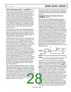
However, if a condition exists where the system analog signal
conditioning circuitry supplies are different to the VDD and
V
SS supplies of the AD7656-1/AD7657-1/AD7658-1, or if the
analog inputs may be applied prior to the AD7656-1/
AD7657-1/AD7658-1 supplies being established, then an analog
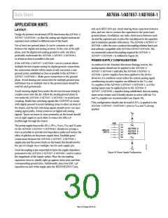
input series resister and Schottky diodes in series with the VDD
and VSS supplies are recommended (see Figure 39).
Avoid running digital lines under the devices because doing so
couples noise onto the die. Allow the analog ground plane to
run under the AD7656-1/AD7657-1/AD7658-1 to avoid noise
coupling. Shield fast-switching signals like CONVST or clocks
with digital ground to avoid radiating noise to other sections of
the board, and the fast switching signals should never run near
analog signal paths. Avoid crossover of digital and analog
signals. Traces on layers in close proximity on the board should
run at right angles to each other to reduce the effect of
feedthrough through the board.
This configuration should also be used if AVCC is applied to the
AD7656-1/AD7657-1/AD7658-1 prior to VDD and VSS being
applied.
V
DD
240Ω
V1
V2
V3
V4
V5
V6
V
DD
The power supply lines to the AVCC, DVCC, VDRIVE, VDD, and VSS pins
on the AD7656-1/AD7657-1/AD7658-1 should use as large a
trace as possible to provide low impedance paths and reduce the
effect of glitches on the power supply lines. Establish good
connections between the AD7656-1/AD7657-1/AD7658-1
supply pins and the power tracks on the board; this should involve
the use of a single via or multiple vias for each supply pin.
AD7656-1/
AD7657-1/
AD7658-1
ANALOG
INPUTS
V
SS
V
SS
Good decoupling is also important to lower the supply impedance
presented to the AD7656-1/AD7657-1/AD7658-1 and to reduce
the magnitude of the supply spikes. Place the decoupling
capacitors close to, ideally right up against, these pins and their
corresponding ground pins. Additionally, place low ESR 1 μF
capacitors on each of the supply pins, the REFIN/REFOUT pin,
Figure 39. Power Supply Configuration
Rev. D | Page 29 of 32

 ROCHESTER [ Rochester Electronics ]