Rx5C348A/B
In the pulse mode, the increment of the second counter is delayed by approximately 92 µs from the
falling edge of clock pulses. Consequently, time readings immediately after the falling edge of clock
pulses may appear to lag behind the time counts of the real-time clocks by approximately 1 second.
Rewriting the second counter will reset the other time counters of less than 1 second, driving the
/INTR pin low.
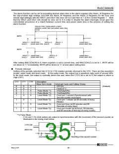
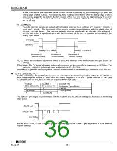
*2) Level Mode:
Periodic interrupt signals are output with selectable interrupt cycle settings of 1 second, 1 minute, 1
hour, and 1 month. The increment of the second counter is synchronized with the falling edge of
periodic interrupt signals. For example, periodic interrupt signals with an interrupt cycle setting of 1
second are output in synchronization with the increment of the second counter as illustrated in the
timing chart below.
CTFG Bit
/INTR Pin
Setting CTFG bit to 0
Setting CTFG bit to 0
(Increment of
second counter)
(Increment of
second counter)
(Increment of
second counter)
*1), *2) When the oscillation adjustment circuit is used, the interrupt cycle will fluctuate once per 20sec. as
follows:
Pulse Mode: The “L” period of output pulses will increment or decrement by a maximum of ±3.784ms. For
example, 1-Hz clock pulses will have a duty cycle of 50 ±0.3784%.
Level Mode: A periodic interrupt cycle of 1 second will increment or decrement by a maximum of ±3.784 ms.
ꢁ
32-kHz CLOCK OUTPUT
For the Rx5C348A, 32.768-kHz clock pulses are output from the 32KOUT pin when either the /CLEN1 bit in
the Control Register 2 or the /CLEN2 bit in the Control Register 1 is set to 0. When both the /CLEN1 and
/CLEN2 bits are set to 0, the 32KOUT pin output is driven high (off).
/CLEN1
/CLEN2
32KOUT PIN
(N-channel Open Drain)
OFF(H)
(D3 at Address Fh)
(D4 at Address Eh)
1
1
0(Default)
*
*
Clock pulses
0(Default)
The 32KOUT pin output is synchronized with the /CLEN1 and /CLEN2 bit settings as illustrated in the timing
chart below.
/CLEN1or2
32KOUT PIN
Max.62.0µs
For the Rx5C348B, 32.768-kHz clock pulses are output from the 32KOUT pin regardless of such internal
register settings.
12345
Rev.2.01
- 36 -

 RICOH [ RICOH ELECTRONICS DEVICES DIVISION ]