RT9214
Application Information
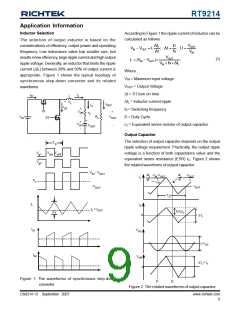
Inductor Selection
According to Figure 1 the ripple current of inductor can be
calculated as follows :
The selection of output inductor is based on the
considerations of efficiency, output power and operating
frequency. Low inductance value has smaller size, but
results in low efficiency, large ripple current and high output
ripple voltage. Generally, an inductor that limits the ripple
current (ΔIL) between 20% and 50% of output current is
appropriate. Figure 1 shows the typical topology of
synchronous step-down converter and its related
waveforms.
ΔI
VOUT
D
V − VOUT = L L ; Δt = ; D =
IN
Δt
fs
VOUT
V × fs× ΔIL
V
IN
(1)
L = (V − VOUT )×
IN
IN
Where :
VIN = Maximum input voltage
VOUT = Output Voltage
Δt = S1 turn on time
i
I
S1
L
L
+
-
V
ΔIL = Inductor current ripple
fS = Switching frequency
D = Duty Cycle
L
I
i
OUT
C
i
S2
+
S1
V
+
r
OR
-
C
V
R
V
S2
IN
L
OUT
+
OC
-
V
rC = Equivalent series resistor of output capacitor
-
C
OUT
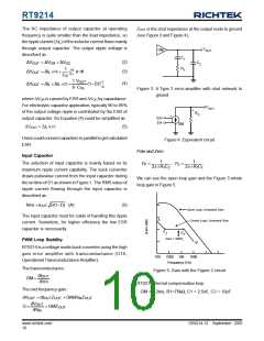
Output Capacitor
The selection of output capacitor depends on the output
ripple voltage requirement. Practically, the output ripple
voltage is a function of both capacitance value and the
equivalent series resistance (ESR) rC. Figure 2 shows
the related waveforms of output capacitor.
T
S
T
V
V
T
g1
ON OFF
g2
V
- V
IN
OUT
di
di
L
dt
V
-V
V
L
IN OUT
OUT
L
i
L
=
=
L
dt
V
L
I
- V
OUT
OUT
T
S
i
i
L
C
I = I
L
OUT
1/2ΔI
ΔI
L
L
0
ΔI
L
i
V
S1
OC
ΔV
OC
i
S2
V
OR
ΔI x r
L
c
0
Figure 1. The waveforms of synchronous step-down
converter
t1
t2
Figure 2. The related waveforms of output capacitor
www.richtek.com
9
DS9214-13 September 2007

 RICHTEK [ RICHTEK TECHNOLOGY CORPORATION ]