RT9214
The AC impedance of output capacitor at operating
frequency is quite smaller than the load impedance, so
the ripple current (ΔIL) of the inductor current flows mainly
through output capacitor. The output ripple voltage is
described as :
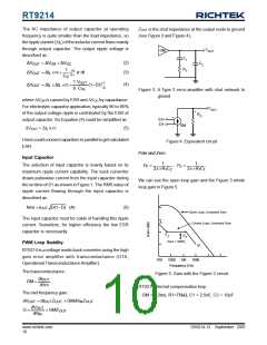
ZOUT is the shut impedance at the output node to ground
(see Figure 3 and Figure 4),
V
GM
OUT
C
R
1
(2)
(3)
ΔVOUT = ΔVOR + ΔVOC
C
2
1
t2
1
ΔVOUT = ΔIL ×rc +
ic dt
∫
t1
CO
1 VOUT
8 COL
ΔVOUT = ΔIL × ΔIL ×rc +
(1−D)TS2
(4)
Figure 3. A Type 2 error-amplifier with shut network to
ground
where ΔVOR is caused by ESR and ΔVOC by capacitance.
For electrolytic capacitor application, typically 90 to 95%
of the output voltage ripple is contributed by the ESR of
output capacitor. So Equation (4) could be simplified as :
V
OUT
+
R
O
+
EA+
EA-
GM
-
(5)
ΔVOUT = ΔIL x rc
Users could connect capacitors in parallel to get calculated
ESR.
Figure 4. Equivalent circuit
Pole and Zero :
1
Input Capacitor
1
2π ×R C
1 1
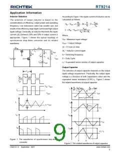
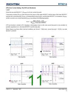
The selection of input capacitor is mainly based on its
maximum ripple current capability. The buck converter
draws pulsewise current from the input capacitor during
the on time of S1 as shown in Figure 1. The RMS value of
ripple current flowing through the input capacitor is
described as :
F =
P
; F =
Z
2π ×R C
1
2
We can see the open loop gain and the Figure 3 whole
loop gain in Figure 5.
(6)
Irms = IOUT D(1−D) (A)
Open Loop, Unloaded Gain
The input capacitor must be cable of handling this ripple
current. Sometime, for higher efficiency the low ESR
capacitor is necessarily.
A
Closed Loop, Unloaded Gain
F
F
Z
P
Gain = GMR1
PWM Loop Stability
B
RT9214 is a voltage mode buck converter using the high
gain error amplifier with transconductance (OTA,
Operational TransconductanceAmplifier).
100
1000 10k
100k
Frequency (Hz)
The transconductance :
Figure 5. Gain with the Figure 2 circuit
dI
OUT
GM =
dVm
RT9214 internal compensation loop :
The mid-frequency gain :
GM = 0.2ms, R1=75kΩ, C1 = 2.5nF, C2 = 10pF
dVOUT = dIOUTZOUT = GMdVINZOUT
dVOUT
G =
= GMZOUT
dV
IN
DS9214-13 September 2007
www.richtek.com
10

 RICHTEK [ RICHTEK TECHNOLOGY CORPORATION ]