RT9214
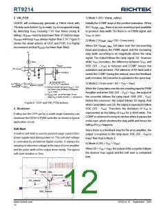
2. VIN_POR
1) Mode 1 (SS< Vramp_valley)
UGATE will continuously generate a 10kHz clock with
1% duty cycle before VIN is ready. VIN is recognized ready
by detecting VOPS crossing 1.5V four times (rising &
falling). ROCSET must be kept lower than 37.5kΩ for large
ROCSET will keep VOPS always higher than 1.5V. Figure 6
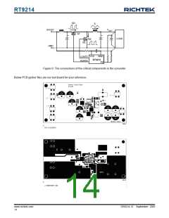
shows the detail actions of OCP and POR. It is highly
recommend-ed that ROCSET be lower than 30kΩ.
Initially the COMP stays in the positive saturation. When
SS< VRAMP_Valley, there is no non-inverting input available
to produce duty width. So there is no PWM signal and
VOUT is zero.
2) Mode 2 (VRAMP_Valley< SS< Cross-over)
When SS>VRAMP_Valley, SS takes over the non-inverting
input and produce the PWM signal and the increasing
duty width according to its magnitude above the ramp
signal. The output follows the ramp signal, SS. However
while VOUT increases, the difference between VOUT and
SSE (SS − VGS) is reduced and COMP leaves the
saturation and declines. The takeover of SS lasts until it
meets the COMP. During this interval, since the feedback
path is broken, the converter is operated in the open loop.
3V
40uA
R
OCSET
PHASE
-
+
OPS
OC
0.4V
10pF
Q2
DISABLE
+
-
Cparasitic
1st 2nd3rd 4th
OPS
waveform
3) Mode3 ( Cross-over< SS < VGS + VREF
)
V
POR_H
+
-
IN
UGATE
PHASE_M
(1) Internal Counter will count (V
> 1.5V)
1.5V
OPS
When the Comp takes over the non-inverting input for PWM
Amplifier and when SSE (SS − VGS) < VREF, the output of
the converter follows the ramp input, SSE (SS − VGS).
Before the crossover, the output follows SS signal. And
when Comp takes over SS, the output is expected to follow
SSE (SS − VGS). Therefore the deviation of VGS is
represented as the falling of VOUT for a short while. The
COMP is observed to keep its decline when it passes the
cross-over, which shortens the duty width and hence the
falling of VOUT happens.
four times (rising & falling) to recognize
V
is ready.
IN
(2) R
canꢀbe set too large. Or canꢀ
OCSET
detect V is ready (counter = 1, not equal 4)
IN
Figure 6. OCP and VIN_POR actions
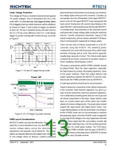
3. Shutdown
Pulling low the OPS pin by a small single transistor can
shutdown the RT9214 PWM controller as shown in typical
application circuit.
Soft Start
Since there is a feedback loop for the error amplifier, the
output’ s response to the ramp input, SSE (SS − VGS) is
lower than that in Mode 2.
A built-in soft-start is used to prevent surge current from
power supply input during power on. The soft-start voltage
is controlled by an internal digital counter. It clamps the
ramping of reference voltage at the input of error amplifier
and the pulse-width of the output driver slowly. The typical
soft-start duration is 3ms.
4) Mode 4 (SS > VGS + VREF
)
When SS > VGS + VREF, the output of the converter follows
the desired VREF signal and the soft start is completed
now.
COMP
V
RAMP_Valley
Cross-over
SS_Internal
VCORE
SSE_Internal
DS9214-13 September 2007
www.richtek.com
12

 RICHTEK [ RICHTEK TECHNOLOGY CORPORATION ]