RT8841
T2 = VBOOT x CSS/ISS1
(2)
pin connects to the negative remote sense pin of CPU
(VCCN) directly. The ErrorAmp compares EAP (= VDAC
VADJ) with the VFB to regulate the output voltage.
−
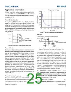
T3 is the dwelling time for VOUT = VBOOT. T3 = 800μs.
T4 is the soft start time from VOUT = VBOOT to VOUT
VDAC
=
C2
.
C
R
FB
FB
C1
T4 ~= |VDAC − VBOOT| x CSS/ISS1
(3)
R1
T5 is the power good delay time, T5 ~= 1600μs.
FB
V
CCP
(Positive remote
sense pin of CPU)
V
0.85V
9.6V
I
TT
OFSP
-
+
VCC12
VCC5
COMP
EA
+
+
DAC
-
-
EAP
V
4.6V
(Negative remote
sense pin of CPU)
V
V
CCN
DAC
FBRTN
ADJ
I
OFSN
SS
R
ADJ
SSQ
V
BOOT
SS
SSQ
Figure 6. Circuit for VOUT Differential Sensing andNo
Load Offset
T1
T2
T3
T4
T5
PWRGD
Figure 5. Soft Start Waveforms
No-Load Offset
Dynamic VID
The RT8841 can accept VID input changing while the
controller is running. This allows the output voltage (VOUT
In Figure 6, IOFSN or IOFSP are used to generate no-load
offset. Either IOFSN or IOFSP is active during normal operation.
It should be noted that users can only enable one polarity
of no-load offset. Do not connect OFS pin to GND and to
VCC5 at the same time. Connect a resistor from OFS pin
to GND to activate IOFSN. IOFSN flows through RADJ from
ADJ pin toGND. In this case, negative no-load offset voltage
(VOFSN) is generated.
)
to change while the DC/DC converter is running and
supplying current to the load. This is commonly referred
to as VID on-the-fly (OTF). A VID OTF can occur under
either light or heavy load conditions. The CPU changes
the VID inputs in multiple steps from the start code to the
finish code. This change can be positive or negative.
Theoretically, VOUT should follow VDAC which is a staircase
waveform. In RT8841, as mentioned in soft start session,
VDAC slew rate is limited by ISS2/CSS when PWRGD = H.
This slew rate limiter works as a low pass filter of VDAC
and makes the bandwidth of VDAC waveform finite. By
smoothening VDAC staircase waveform, VOUT will no longer
overshoot or undershoot. On the other hand, CSS will
increase the settling time of VOUT during VIDOTF. In most
cases, 1nF to 30nF ceramic capacitor is suitable for CSS.
VOFSN = IOFSN x RADJ = 0.8 x RADJ/ROFS
(4)
Connect a resistor from OFS pin to VCC5 to activate IOFSP
.
IOFSP flows through RFB from the VCCP to FB pin. In this
case, positive no-load offset voltage (VOFSP) is generated.
When positive no-load offset is selected, the RT8841 will
generate another internal 8uAcurrent source to eliminate
dead zone problem of droop function. This 8uA current
will be injected intoADJ resistors, producing a small initial
negative no-load offset. Therefore, when OFS pin is
connected to VCC5 through a resistor, the positive no-
load offset can be calculated as :
Output Voltage Differential Sensing
The RT8841 uses differential sensing by a high gain low
offset ErrorAmp. The CPU voltage is sensed between the
VOFSP = IOFSP ×RFB −8uA×RADJ
(5)
RFB
= 6.4×
−8uA×RADJ
FB and FBRTNpins.Aresistor (RFB) connects FB pin and
the positive remote sense pin of the CPU (VCCP). FBRTN
ROFS
www.richtek.com
26
DS8841-01 April 2011

 RICHTEK [ RICHTEK TECHNOLOGY CORPORATION ]