RT8841
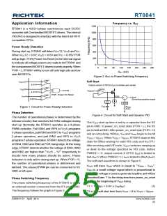
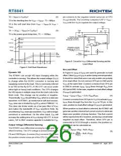
Frequency vs. RRT
Application Information
1200
1000
800
600
400
200
0
RT8841 is a 4/3/2/1-phase synchronous buck DC/DC
converter with 2 embedded MOSFET drivers. The internal
VIDDAC is designed to interface with the Intel 8-bit VR11
compatible CPUs.
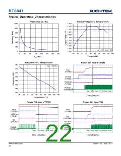
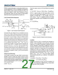
Power Ready Detection
During start-up, RT8841 will detect VCC12, VCC5 and VTT.
When VCC12 > 9.6V, VCC5 > 4.6V and VTT > 0.85V POR
will go high. POR (Power On Reset) is the internal signal
to indicate all voltage powers are ready to let RT8841 and
the companioned MOSFET drivers to work properly. When
POR = L, RT8841 will try to turn off both high side and low
side MOSFETs.
0
40
80
120
160
200
240
280
RRT ((kkΩoh)m)
Figure 2. RRT vs Phase Switching Frequency
Soft Start
CMP
V
12
5
+
-
CC
9.6V
Output current of OPSS (I ) is limited and variant
SS
CMP
CMP
V
+
-
OPSS
CC
POR
V
DAC
+
4.6V
-
POR : Power On Reset
V
+
-
SSQ
TT
EAP
(ErrorAmp positive input)
+
-
0.85V
SS
ADJ
C
SS
R
ADJ
NTC
Figure 1. Circuit for Power ReadyDetection
Phase Detection
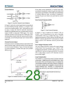
Figure 4. Circuit for Soft Start andDynamic VID
The number of operational phases is determined by the
internal circuitry that monitors the ISNx voltages during
start up. Normally, the RT8841 operates as a 4-phase
PWM controller. Pull ISN4 and ISP4 to VCC5 programs
3-phase operation, pull ISN3 and ISP3 to VCC5 programs
The VOUT start-up time is set by a capacitor from the SS
pin to GND. In power_on_reset state (POR = L), the SS
pin is held atGND.After power_on_reset stae (POR = H)
and an extra delay 1600us, VSS and VSSQ begin to rise till
VSSQ = VBOOT. When VSSQ = VBOOT, RT8841 stays in this
state for 800us waiting for valid VID code sent by CPU.
After receiving valid VIDcode, VOUT continues ramping up
or down to the voltage specified by VID code. Before
PWRGD = H, output current of OPSS (ISS) is limited to
8uA(ISS1). When PWRGD= H, ISS is limited to 80uA(ISS2).
The soft start waveform is shown in Figure 5.
2-phase operation, and pull ISN2 and ISP2 to VCC
5
programs 1-phase operation. RT8841 detects the voltage
of ISN4, ISN3 and ISN2 at POR rising edge.At the rising
edge, RT8841 detects whether the voltage of ISN4, ISN3
and ISN2 are higher than “VCC5 − 1V” respectively to
decide how many phases should be active. Phase
detection is only active during start up. When POR = H,
the number of operational phases is determined and
latched. The unused PWM pin can be connected to 5V,
GND or left open.
VOUT will trace VEAP which is equal to “VSSQ − VADJ”.
VADJ is a small voltage signal which is proportional to
IOUT. This voltage is used to generate loadline and will be
described later. T1 is the delay time from power_on_reset
state to the beginning of VOUT rising.
Phase Switching Frequency
The phase switching frequency of the RT8841 is set by
an external resistor connected from the RT pin to GND.
The frequency follows the graph in Figure 2.
T1 = 1600μs + 0.6V x CSS/ISS1
(1)
T2 is the soft start time from VOUT = 0 to VOUT = VBOOT
.
DS8841-01 April 2011
www.richtek.com
25

 RICHTEK [ RICHTEK TECHNOLOGY CORPORATION ]