RT8296A
Thermal Considerations
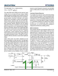
derating curves allows the designer to see the effect of
rising ambient temperature on the maximum power
dissipation allowed.
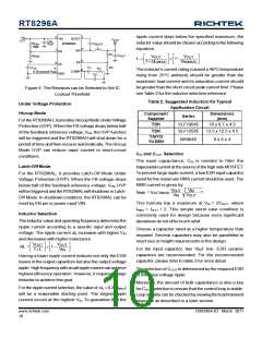
For continuous operation, do not exceed the maximum
operation junction temperature 125°C. The maximum
power dissipation depends on the thermal resistance of
IC package, PCB layout, the rate of surroundings airflow
and temperature difference between junction to ambient.
The maximum power dissipation can be calculated by
following formula :
2.2
Four Layer PCB
2.0
1.8
Copper Area
1.6
1.4
1.2
1.0
0.8
0.6
0.4
0.2
0.0
2
70mm
2
50mm
2
30mm
2
PD(MAX) = (TJ(MAX) - TA ) / qJA
10mm
Min.Layout
Where TJ(MAX) is the maximum operation junction
temperature , TA is the ambient temperature and the qJAis
the junction to ambient thermal resistance.
For recommended operating conditions specification of
RT8296A, the maximum junction temperature is 125°C.
The junction to ambient thermal resistance qJA is layout
dependent. For PSOP-8 package, the thermal resistance
qJA is 75°C/W on the standard JEDEC 51-7 four-layers
thermal test board. The maximum power dissipation at
TA = 25°C can be calculated by following formula :
0
25
50
75
100
125
Ambient Temperature (°C)
Figure 7. Derating Curves for RT8296A Package
PD(MAX) = (125°C - 25°C) / (75°C/W) = 1.333W
(min.copper area PCB layout)
PD(MAX) = (125°C - 25°C) / (49°C/W) = 2.04W
(70mm2copper area PCB layout)
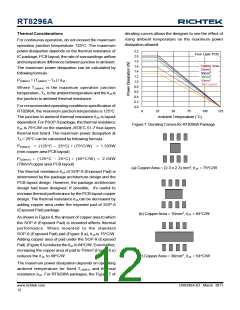
(a) CopperArea = (2.3 x 2.3) mm2,qJA = 75°C/W
The thermal resistance qJA of SOP-8 (Exposed Pad) is
determined by the package architecture design and the
PCB layout design. However, the package architecture
design had been designed. If possible, it's useful to
increase thermal performance by the PCB layout copper
design. The thermal resistance qJA can be decreased by
adding copper area under the exposed pad of SOP-8
(Exposed Pad) package.
(b) CopperArea = 10mm2,qJA = 64°C/W
As shown in Figure 6, the amount of copper area to which
the SOP-8 (Exposed Pad) is mounted affects thermal
performance. When mounted to the standard
SOP-8 (Exposed Pad) pad (Figure 6.a), qJA is 75°C/W.
Adding copper area of pad under the SOP-8 (Exposed
Pad) (Figure 6.b) reduces the qJA to 64°C/W. Even further,
increasing the copper area of pad to 70mm2 (Figure 6.e)
reduces the qJA to 49°C/W.
(c) Copper Area = 30mm2 ,qJA = 54°C/W
The maximum power dissipation depends on operating
ambient temperature for fixed TJ(MAX) and thermal
resistance qJA. For RT8296A packages, the Figure 7 of
www.richtek.com
12
DS8296A-03 March 2011

 RICHTEK [ RICHTEK TECHNOLOGY CORPORATION ]