RT8296A
ripple current stays below the specified maximum, the
inductor value should be chosen according to the following
equation :
1
3
2
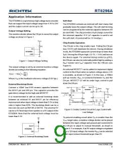
V
12V
IN
VIN
BOOT
V
OUT
8V
C
IN
10µF
C
R
100k
RT8296A
BOOT
L
EN1
7
SW
EN
R1
R2
C
OUT
R
EN2
é
ù é
´ 1-
ù
V
f ´ DI
V
OUT
V
IN(MAX)
OUT
L =
ê
ú ê
ú
5
6
L(MAX)
FB
ë
û ë
û
8
SS
C
C
C
SS
4,
R
C
The inductor's current rating (caused a 40°C temperature
rising from 25°C ambient) should be greater than the
maximum load current and its saturation current should
be greater than the short circuit peak current limit. Please
see Table 2 for the inductor selection reference.
COMP
9 (Exposed Pad)
GND
C
P
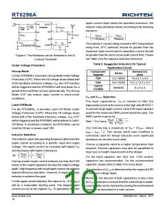
Figure 4. The Resistors can be Selected to Set IC
Lockout Threshold
Table 2. Suggested Inductors for Typical
Application Circuit
Under Voltage Protection
Hiccup Mode
Component
Supplier
Dimensions
(mm)
Series
For the RT8296AH, it provides Hiccup Mode UnderVoltage
Protection (UVP). When the FB voltage drops below half
of the feedback reference voltage, VFB, the UVP function
will be triggered and the RT8296AH will shut down for a
period of time and then recover automatically. The Hiccup
Mode UVP can reduce input current in short-circuit
conditions.
TDK
TDK
VLF10045
SLF12565
10 x 9.7 x 4.5
12.5 x 12.5 x 6.5
TAIYO
YUDEN
NR8040
8 x 8 x 4
CIN and COUT Selection
The input capacitance, CIN, is needed to filter the
trapezoidal current at the source of the high side MOSFET.
To prevent large ripple current, a low ESR input capacitor
sized for the maximum RMS current should be used. The
RMS current is given by :
Latch-Off Mode
For the RT8296AL, it provides Latch-Off Mode Under
Voltage Protection (UVP). When the FB voltage drops
below half of the feedback reference voltage, VFB, UVP
will be triggered and the RT8296AL will shutdown in Latch-
Off Mode. In shutdown condition, the RT8296AL can be
reset by EN pin or power input VIN.
V
V
V
OUT
IN
I
= I
- 1
RMS
OUT(MAX)
V
OUT
IN
This formula has a maximum at VIN = 2VOUT, where
IRMS = IOUT / 2. This simple worst case condition is
commonly used for design because even significant
deviations do not offer much relief.
Inductor Selection
The inductor value and operating frequency determine the
ripple current according to a specific input and output
voltage. The ripple current DIL increases with higher VIN
and decreases with higher inductance.
Choose a capacitor rated at a higher temperature than
required. Several capacitors may also be paralleled to
meet size or height requirements in the design.
V
f ´ L
V
OUT ù
é
ë
OUT ù é
´ 1-
ú ê
DIL =
ê
ú
For the input capacitor, two 10mF low ESR ceramic
capacitors are recommended. For the recommended
capacitor, please refer to table 3 for more detail.
V
IN
û ë
û
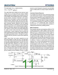
Having a lower ripple current reduces not only the ESR
losses in the output capacitors but also the output voltage
ripple. High frequency with small ripple current can achieve
highest efficiency operation. However, it requires a large
inductor to achieve this goal.
The selection of COUT is determined by the required ESR
to minimize voltage ripple.
Moreover, the amount of bulk capacitance is also a key
for COUT selection to ensure that the control loop is stable.
Loop stability can be checked by viewing the load transient
response as described in a later section.
For the ripple current selection, the value of DIL=0.24(IMAX
)
will be a reasonable starting point. The largest ripple
current occurs at the highest VIN. To guarantee that the
www.richtek.com
10
DS8296A-03 March 2011

 RICHTEK [ RICHTEK TECHNOLOGY CORPORATION ]