RT6343
Application Information
A general RT6343 application circuit is shown in typical
application circuit section. External component selection
is largely driven by the load requirement and begins with
the switching frequency selection by using external resistor
RRT/SYNC. Next, the inductor L, the input capacitor CIN,
the output capacitor COUT and freewheel diode are chosen.
Next, feedback resistors and compensation circuit are
selected to set the desired output voltage and crossover
frequency, and the bootstrap capacitor CBOOT can be
selected. Finally, the remaining optional external
components can be selected for functions such as the
EN, external soft-start, PGOOD, and synchronization.
shows minimum off-time calculation with loss terms
consideration :
V
+ I
R + V
OUT
OUT_MAX
L
D
1
V
I
R
V
D
IN_MIN
OUT_MAX
DS(ON)_H
t
OFF_MIN
f
SW
where RDS(ON)_H is the on-resistance of the high-side
MOSFET; VD is the forward conduction voltage of the
freewheel diode; RL is the DC resistance of inductor.
The switching frequency fSW is set by the external resistor
RRT/SYNC connected between the RT/SYNC pin and
ground. The failure mode and effects analysis (FMEA)
consideration is applied to the RT/SYNC pin setting to
avoid abnormal switching frequency operation at failure
conditions. It includes failure scenarios of short-circuit to
ground and the pin is left open. The switching frequency
will be 900kHz (typically) when the RT/SYNC pin is
shorted to ground, and 240kHz (typically) when the pin is
left open. The equation below shows the relation between
setting frequency and the RRT/SYNC value.
Switching Frequency Setting
The RT6343 offers adjustable switching frequency setting
and the switching frequency can be set by using external
resistor RRT/SYNC. The switching frequency range is from
100kHz to 2.5MHz. The selection of the operating
frequency is a trade-off between efficiency and component
size. High frequency operation allows the use of smaller
inductor and capacitor values. Operation at lower
frequencies improves efficiency by reducing internal gate
charge and transition losses, but requires larger inductance
values and/or capacitance to maintain low output ripple
voltage. The additional constraints on operating frequency
are the minimum on-time and minimum off-time. The
minimum on-time, tON_MIN, is the smallest duration of time
in which the high-side switch can be in its “on” state.
The minimum on-time of the RT6343 is 100ns (typically).
In continuous mode operation, the maximum operating
frequency, fSW_MAX, can be derived from the minimum on-
time according to the formula below :
120279
R
=
RT/SYNC (k)
1.033
f
SW
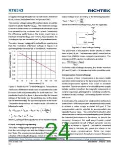
where fSW (kHz) is the desired setting frequency. It is
recommended to use 1% tolerance or better, and the
temperature coefficient of 100 ppm or less resistors. Figure
3 shows the relationship between switching frequency and
the RRT/SYNC resistor.
1200
1000
800
600
400
200
0
V
OUT
f
=
SW_MAX
t
V
IN_MAX
ON_MIN
where VIN_MAX is the maximum operating input voltage.
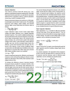
The minimum off-time, tOFF_MIN, is the smallest amount of
time that the RT6343 is capable of tripping the current
comparator and turning the high-side MOSFET back off.
The minimum off-time of the RT6343 is 130ns (typically).
If the switching frequency should be constant, the required
off-time needs to be larger than minimum off-time. Below
0
500
1000
1500
2000
2500
fSW (kHz)
Figure 3. Switching Frequency vs. RRT/SYNC
Copyright 2019 Richtek Technology Corporation. All rights reserved.
©
is a registered trademark of Richtek Technology Corporation.
DS6343-00 October 2019
www.richtek.com
21

 RICHTEK [ RICHTEK TECHNOLOGY CORPORATION ]