RT5779A/B
GND
GND
C
IN
V
IN
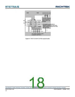
The input capacitor
must be placed as
close to the IC as
possible
EN
FB
PGOOD
R2
R1
VIN
LX
AGND
VOUT
LX should be connected to
inductor by wide and short trace.
Keep sensitive components away
from this trace.
PGND
L
C
OUT
V
OUT
The output capacitor must
be placed near the IC
Figure 6. TSOT-23-8 (FC) PCB LayoutGuide
Copyright 2017 Richtek Technology Corporation. All rights reserved.
©
is a registered trademark of Richtek Technology Corporation.
www.richtek.com
18
DS5779A/B-00 October 2017

 RICHTEK [ RICHTEK TECHNOLOGY CORPORATION ]