RX62N Group, RX621 Group
3. Address Space
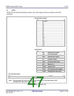
3.2
External Address Space
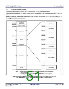
The external address space is classified into CS areas (CS0 to CS7) and SDRAM area (SDCS).
The CS area is divided into up to 8 areas (CS0 to CS7), each corresponding to the CSi# signal output from a CSi# (i = 0
to 7) pin.
Figure 3.2 shows the address ranges corresponding to the individual CS areas (CS0 to CS7) and SDRAM area (SDCS)
in on-chip ROM disabled extended mode.
0100 0000h
0000 0000h
0001 8000h
On-chip RAM
Reserved area*1
CS7 (16 Mbytes)
CS6 (16 Mbytes)
CS5 (16 Mbytes)
CS4 (16 Mbytes)
CS3 (16 Mbytes)
CS2 (16 Mbytes)
CS1 (16 Mbytes)
0008 0000h
Peripheral I/O registers
01FF FFFFh
0200 0000h
0010 0000h
02FF FFFFh
0300 0000h
Reserved area*1
03FF FFFFh
0400 0000h
0100 0000h
External address space
(CS area)
04FF FFFFh
0500 0000h
0800 0000h
1000 0000h
05FF FFFFh
0600 0000h
External address space
(SDRAM area)
06FF FFFFh
0700 0000h
07FF FFFFh
0800 0000h
Reserved area*1
SDCS (128 Mbytes)
0FFF FFFFh
FF00 0000h
FF00 0000h
FFFF FFFFh
2
External address space*
CS0 (16 Mbytes)
(CS area)
FFFF FFFFh
Notes: 1. Reserved areas should not be accessed, since the correct operation of LSI is not guaranteed
if they are accessed.
2. The CS0 area is disabled in on-chip ROM enabled extended mode.
In this mode, the address space for addresses above 1000 0000h is as shown in figure 4.1.
Figure 3.2 Correspondence between External Address Spaces, CS Areas (CS0 to CS7),
and SDRAM area (SDCS) (In On-Chip ROM Disabled Extended Mode)
R01DS0052EJ0110 Rev.1.10
Feb 10, 2011
Page 51 of 146

 RENESAS [ RENESAS TECHNOLOGY CORP ]